Flared leg precast concrete bridge system

a precast concrete and bridge technology, applied in bridges, bridge structural details, sewer pipelines, etc., can solve the problems of difficult production driven environment, high production cost, and inability to meet the needs of construction, so as to reduce the effective span of the resulting structure, reduce the bending moment, and minimize the production set-up and stripping (form removal) time

Inactive Publication Date: 2009-07-23
COUNTY MATERIALS CORP +1
View PDF26 Cites 26 Cited by
  • Summary
  • Abstract
  • Description
  • Claims
  • Application Information

AI Technical Summary

Benefits of technology

[0010]Effective flare angles, spans and rises can be individually adjusted to accommodate a wide range of waterway cross sectional dimensions, flow paths and volume-of-flow requirements. The unique geometric shape of the system reduces the resulting structure's effective span at the top of the structure by sixty to ninety percent as compared to prior art systems. The angular legs reduce the bending moments developed in the structure, but still realize the contributory benefits from the lateral soil support provided by the surrounding soil without being highly dependent upon it.
[

Problems solved by technology

However, both the prior art flattop and arched-top bridge systems derive a significant degree of their structural capacity from the support provided by backfill material and are thu

Method used


Image

  • Flared leg precast concrete bridge system
  • Flared leg precast concrete bridge system
  • Flared leg precast concrete bridge system

Examples


Embodiment Construction

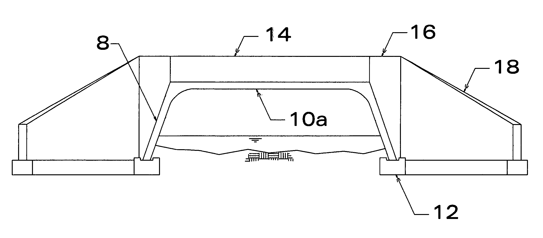
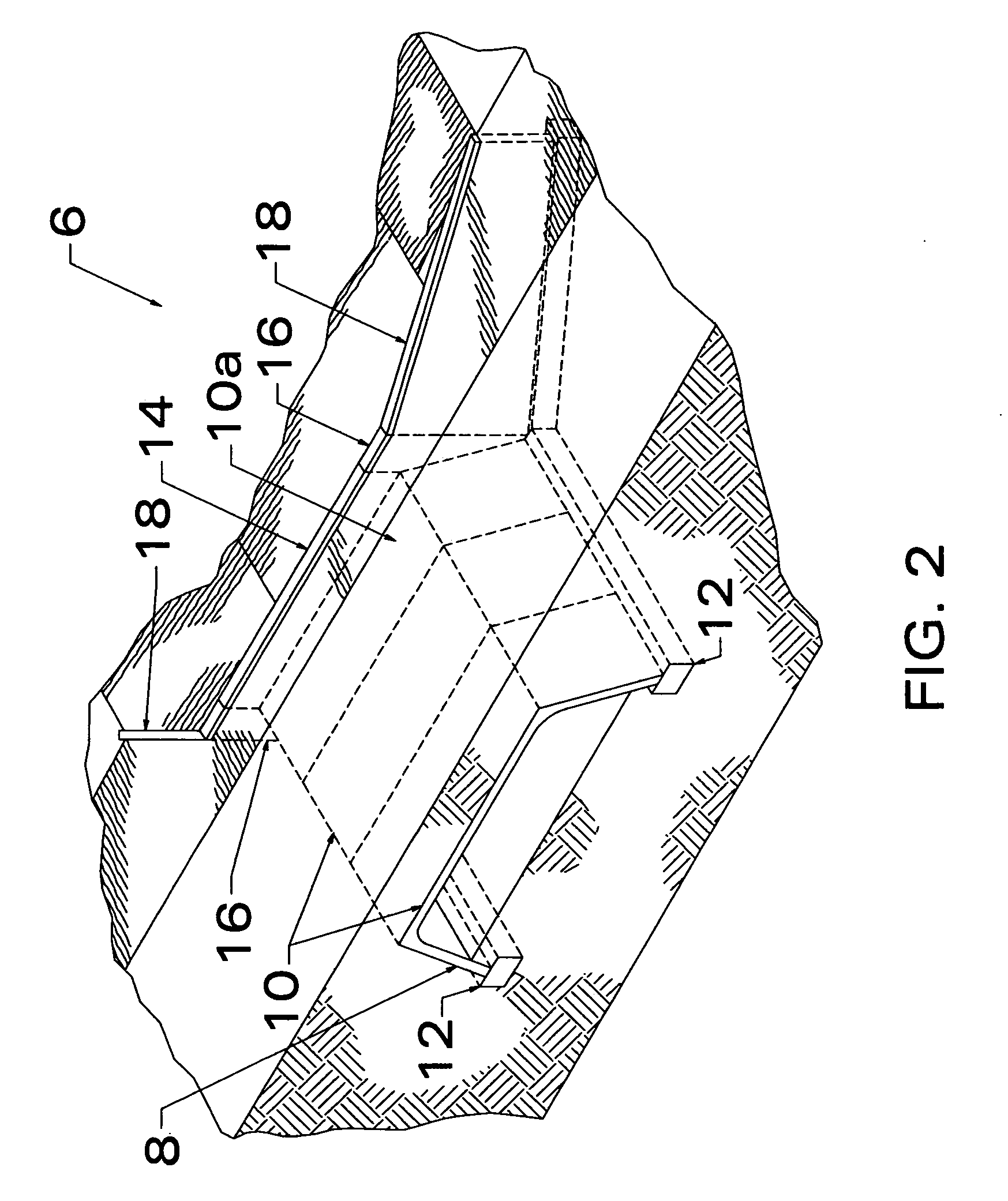
[0024]FIGS. 2, 6 illustrate a preferred embodiment bridge assembly 6 constructed by way of the present invention system. FIGS. 3, 4 and 5 depict preferred embodiment precast sections used in the construction of bridge assembly 6. As shown by these figures, bridge 6 comprises a series of precast elemental concrete sections 10 that are placed in face-to-face parallel alignment. The leg members 8 of each section sit atop two parallel, continuous concrete strip footers 12 that are formed in trenches and cast into the ground. As shown in FIG. 4 concrete strip footer 12 is cast with recess 13 that is sized to receive bottom portion 31 of leg 8. After placement, leg 8 is locked in-place onto footer 12 with cementitious grout. Depending upon site characteristics or other requirements, strip footers 12 may be connected by a cast-in-place concrete slab (not shown).

[0025]As shown in FIG. 4, legs 8 depend angularly from top slab 15 at an effective flare angle A as measured from the horizontal. ...


PUM


Abstract

A concrete building system includes a set of parallel spaced apart strip footers and one or more precast concrete sections supported by the footers in a predetermined alignment. Each precast concrete section has a top slab integrally connected to a pair of equally flared legs. Each leg depends from an end of the top slab at an effective flare angle to form a corner. The precast section includes haunch sections formed between the top slab and each leg resulting in a corner thickness greater than the uniform thickness of the angled leg to which it is integrally formed and the top member. The length of the effective span of each section varies between 60 and 90 percent of the distance between the bottom-of-leg span. The sections can be used to construct bridges, culverts, underground storage units, fluid detention units and dam structures.

Description

CROSS REFERENCE TO RELATED APPLICATION[0001]Not applicable.STATEMENT REGARDING FEDERALLY SPONSORED RESEARCH OR DEVELOPMENT[0002]Not applicable.SEQUENCE LISTING, TABLE OR COMPUTER PROGRAM ON COMPACT DISC[0003]Not applicable.FIELD OF INVENTION[0004]This invention relates generally to precast concrete structures and more particularly to precast concrete bridge and culvert units.BACKGROUND OF THE INVENTION[0005]It is known in the art to use precast concrete building systems in the construction of culverts and bridges. The structures built according to these systems are composed of one or more elemental sections successively placed adjacent to one another. In this regard the individual sections are placed side-by-side in the ground to form, for example, a bridge beneath traffic-ways for road-over-road or road-over-stream crossings. The elemental sections can also be used to construct culverts and underground storage vaults. By precasting multiple sections offsite for subsequent erection ...

Claims


Application Information

Patent Timeline
IPC IPC(8): E01D6/00E02D27/32E01F5/00E01D19/00
CPCE01F5/005
Inventor BORESI, GLENNON J.MICHELS, STEVEN
Owner COUNTY MATERIALS CORP
Why Eureka
Try Eureka