Temperature control device and method

a technology of temperature control device and temperature control method, which is applied in the direction of combustion control, gaseous heating fuel, domestic stoves or ranges, etc., can solve the problems of not including means in barbecues, grills and other cooking or heating apparatus

Active Publication Date: 2009-07-23
WOLFEDALE ENG
View PDF59 Cites 55 Cited by
  • Summary
  • Abstract
  • Description
  • Claims
  • Application Information

AI Technical Summary

Benefits of technology

[0004]In accordance with a broad aspect of the present invention there is provided a temperature control system for controlling the rate of flow of a flammable fluid at generally constant pressure. The system may include a flow control apparatus that is free of a regulator mechanism, for affecting the flow of the fluid. The flow control apparatus may be operable between at least a first flow rate and a second flow rate, and may have at least one upstream opening and at least one downstream opening. The system may also include a first burner in fluid communication with the downstream opening of the flow control apparatus and a conduit in fluid communication at one end thereof with the upstream opening of the flow control apparatus, and configured at the other end thereof for connection to a fuel supply...

Problems solved by technology

Traditionally, barbecues, grills and other cooking or heating apparatus have not incl...

Method used


Image

  • Temperature control device and method
  • Temperature control device and method
  • Temperature control device and method

Examples


Embodiment Construction

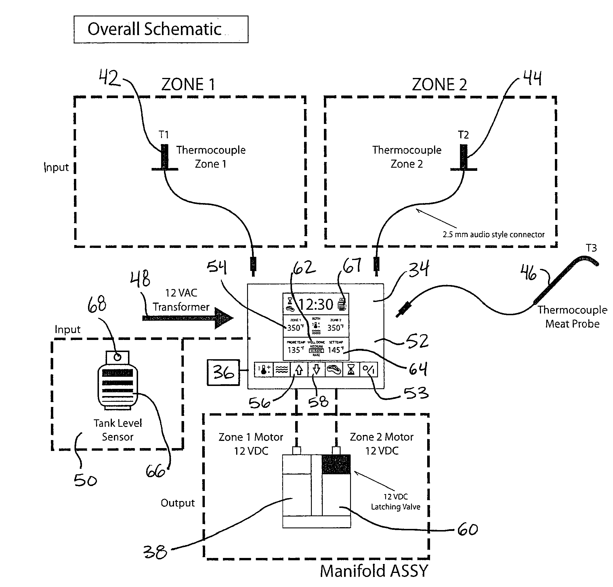
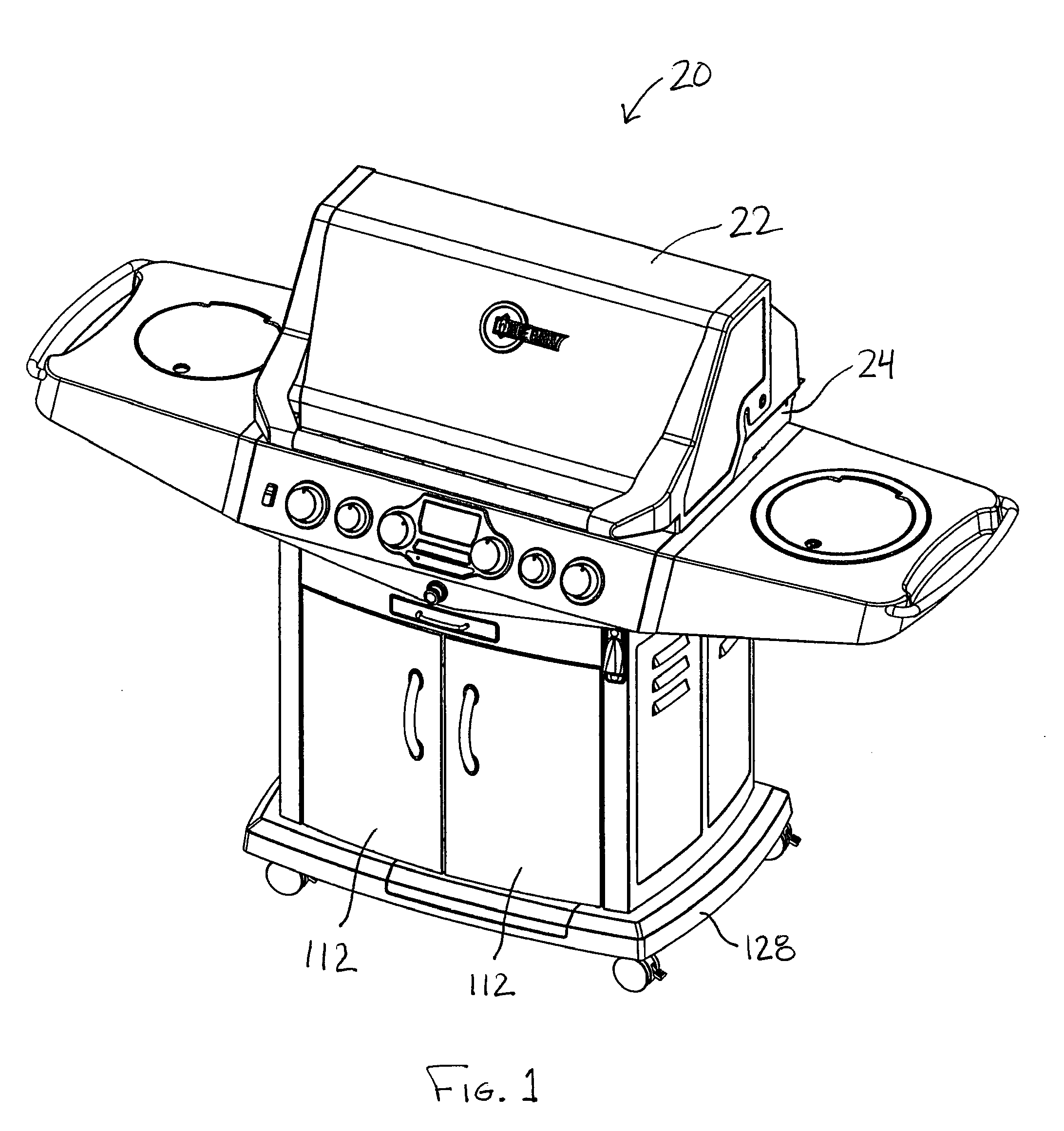
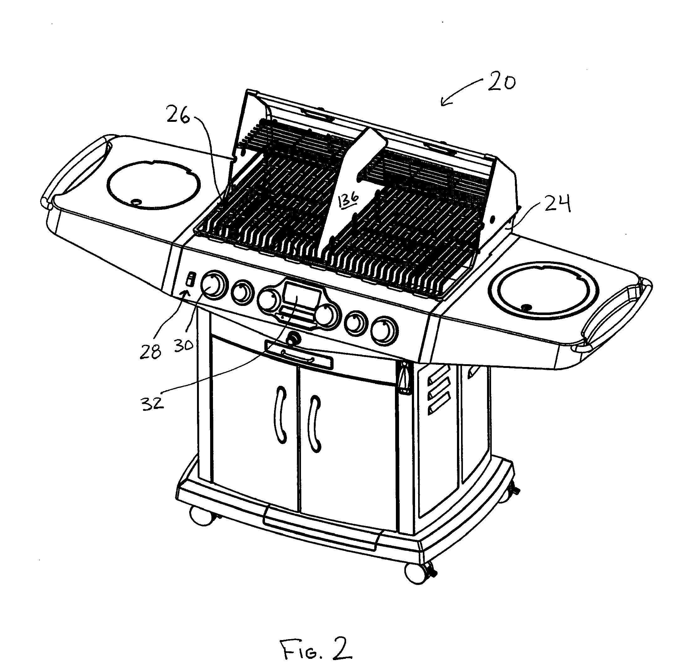
[0113]Similar references are used in different figures to denote similar components. The disclosed temperature control apparatus may facilitate control of an internal temperature of a gas fuelled appliance, such as an outdoor gas barbeque. Alternatively, the apparatus may be employed to facilitate the control of energy output of any gas fueled energy generation device such as a heater or fireplace. The description herein is made in the context of a gas fuelled barbeque, but the disclosed temperature control apparatus may be applied to any manner of appliance, including gas fuelled appliances such as stoves, fireplaces, fire pits, heaters, and fryers.

[0114]In general, the temperature control apparatus permits a user to input a desired temperature set-point. The temperature control apparatus then automatically controls the flow rate of gas into the barbeque to achieve the desired temperature. This may permit greater precision in the cooking of food with a gas fuelled appliance. For ex...


PUM


Abstract

A temperature control system for safely controlling the rate of flow of a flammable fluid at generally constant pressure is disclosed. The system may include a flow control apparatus that is free of a regulator mechanism, for affecting the flow of the fluid. The flow control apparatus may be operable between at least a first flow rate and a second flow rate, and may have at least one upstream opening and at least one downstream opening. The system may also include a first burner in fluid communication with the downstream opening of the flow control apparatus and a conduit in fluid communication at one end thereof with the upstream opening of the flow control apparatus, and configured at the other end thereof for connection to a fuel supply. A thermocouple may be located in the vicinity of the burner or an appliance used in conjunction with the burner. The thermocouple converts a sensed thermal state into an electrical signal. An electronic controller, in communication with the flow control apparatus, for activating the flow control apparatus to one of said first and second flow rates, and being in communication with the thermocouple for receiving the electrical signal from the thermocouple is also provided. An interface connected to the controller for manually inputting a desired temperature may be included, wherein the controller is operable to automatically cycle the flow control apparatus between the first and second flow rates until the temperature sensed by the thermocouple is similar to the desired temperature.

Description

RELATED APPLICATIONS[0001]This application claims priority to prior pending Patent Co-operation Treaty Application having Serial No. PCT / CA2007 / 002085, filed Nov. 16, 2007; pending U.S. patent application Ser. No. 12 / 000,163, filed Dec. 10, 2007; and pending Canadian Patent Application No. 2,613,858, filed Dec. 10, 2007, all the specifications of which prior applications are incorporated herein by reference.FIELD OF THE INVENTION[0002]The invention relates to a temperature control apparatus, and is particularly concerned with a TEMPERATURE CONTROL APPARATUS AND METHOD for a grill, barbeque, fryer, heater, patio heater, fireplace, fire pit / bowl, or any other apparatus which includes a energy source that may be controlled.BACKGROUND OF THE INVENTION[0003]Traditionally, barbecues, grills and other cooking or heating apparatus have not included means for automatically managing the temperature of the energy output by the apparatus. Control of temperature is often managed manually by obse...

Claims


Application Information

Patent Timeline
IPC IPC(8): F24C3/00
CPCA47J27/62A47J37/0713A47J37/0786G05D23/2217F23N5/102F23N2037/10F23N2041/08F23N1/002G05D23/1919G05D23/22F24C7/08A47J36/321F23N2237/10F23N2241/08
Inventor BARKHOUSE, SYDNEYMCKENZIE, STUART T.
Owner WOLFEDALE ENG
Why Eureka
Try Eureka