
Removing Volatile Vapors From A Storage Vessel

a technology for storage vessels and volatile vapors, applied in the direction of liquid handling, separation processes, cleaning using liquids, etc., can solve the problems of high cost of adequate water for such facilities and severe environmental hazards, and achieve the effect of preventing stagnation of vapor and increasing the velocity of gas

Inactive Publication Date: 2009-07-23
HILLIARD EMISSION CONTROLS
View PDF19 Cites 8 Cited by
  • Summary
  • Abstract
  • Description
  • Claims
  • Application Information

AI Technical Summary

Benefits of technology

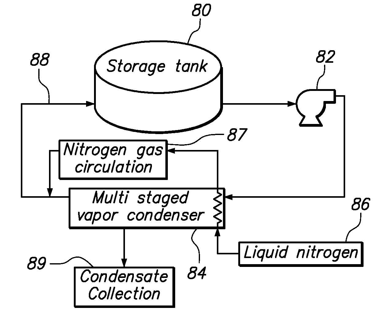
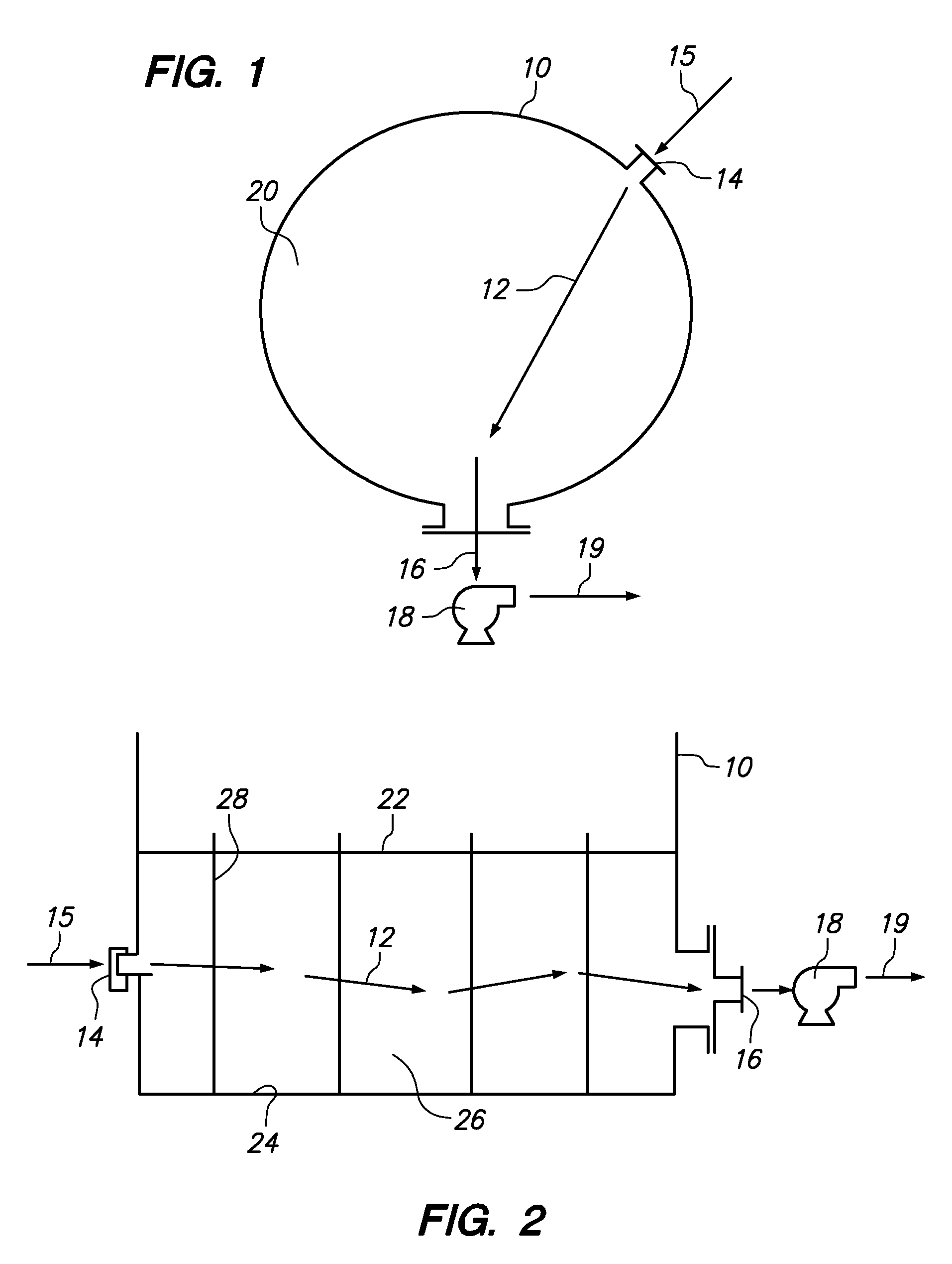
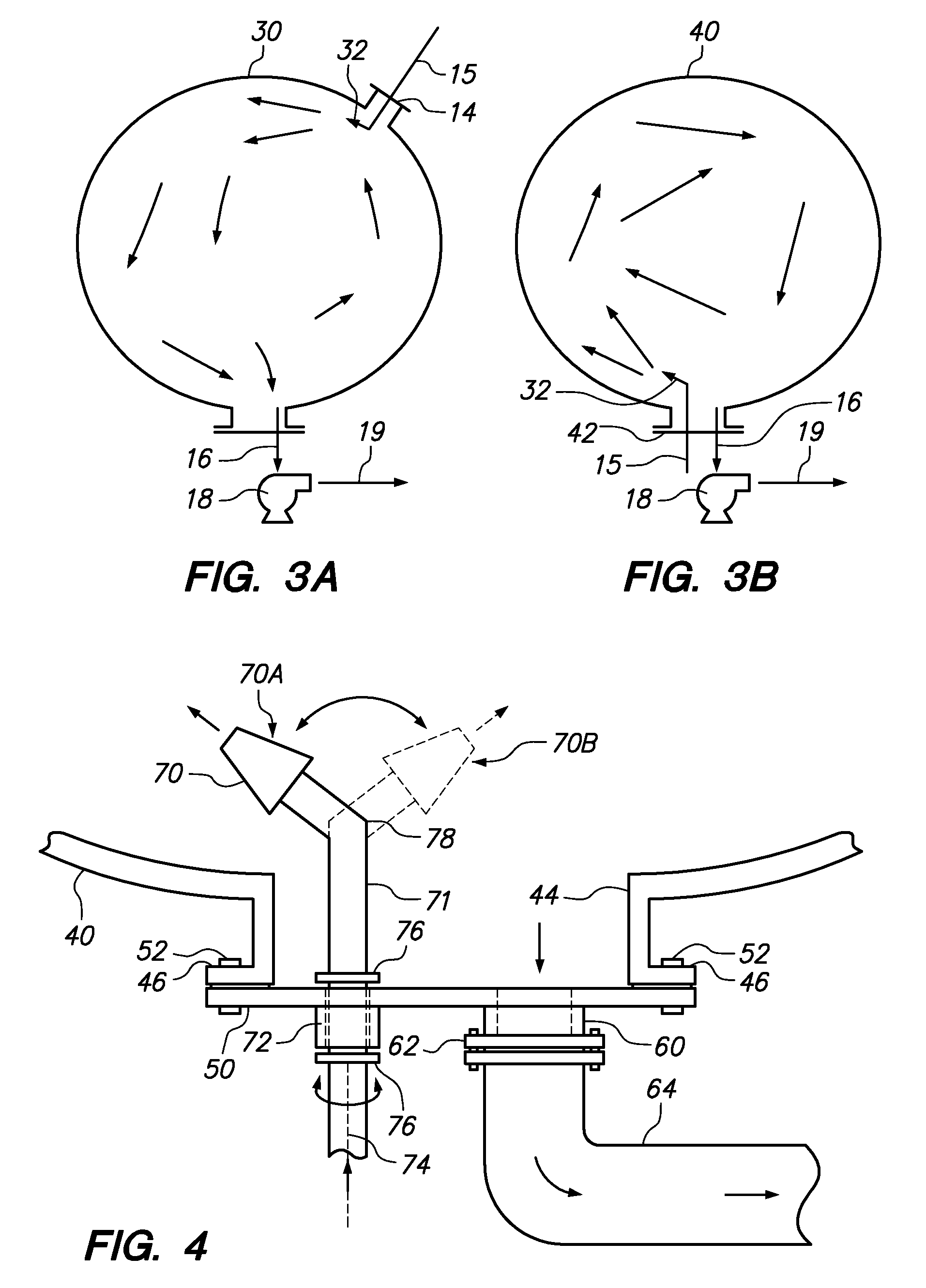
"The present invention provides a method and system for removing vapor from a storage tank. The method involves introducing a stream of gas into the tank to mix with the vapor, and withdrawing a mixture of the vapor and gas through an outlet port. The nozzle used for introducing the gas is designed to prevent stagnation of the vapor in the tank. The system includes a gas mover, an abatement device, a source of pressurized gas, and a nozzle. The nozzle can be automatically adjusted to vary its orientation. The system may also include a recycle conduit to return gas and / or uncondensed vapor to the tank. The technical effects of this invention include improved efficiency in removing vapor from storage tanks and reduced emissions of volatile organic compounds."

Problems solved by technology

Emissions handled in this manner lead to severe environmental hazards.
Adequate water for such facilities may be expensive due to limited water resources or to restrictions concerning the discharge, reuse or recycling of the residual flush water.

Method used


Image

  • Removing Volatile Vapors From A Storage Vessel
  • Removing Volatile Vapors From A Storage Vessel
  • Removing Volatile Vapors From A Storage Vessel

Examples


Embodiment Construction

[0020]One embodiment of the invention provides a method of removing vapor from a storage tank. The method comprises introducing a stream of gas into the storage tank in a manner that causes mixing of the vapor within the tank, and withdrawing a mixture of the vapor and the gas from the storage tank through an outlet port.

[0021]The gas used to cause mixing of the vapor may be any gas that is compatible with the vapor and / or the liquid present in the storage tank, and with any downstream processing of the vapor or liquid that may occur subsequent to its removal from the storage tank. In one embodiment, the preferred gas is air. However, if the volatile vapor is reactive with oxygen in air, then an inert gas, such as nitrogen, may be used. The selected gas may be supplied under pressure from a compressed gas storage container or from a gas mover, such as a compressor or a blower. Other gases or vapors may be used for the purpose of mixing on the basis of their chemical compatibility wi...


PUM

PropertyMeasurementUnit
circumferenceaaaaaaaaaa
vapor concentrationaaaaaaaaaa
volatileaaaaaaaaaa

Abstract

A method and apparatus to remove vapor from a storage tank comprising introducing a stream of gas into the storage tank to cause mixing of the vapor within the tank. The stream of gas is preferably introduced into the storage tank through a gas nozzle that increases the velocity of the gas. Furthermore, the gas nozzle may have a fixed or variable orientation that introduces the stream of gas to flow into a region of the storage tank to prevent retention of the vapor in that region. A mixture of the vapor and the gas is withdrawn from the storage tank through an outlet port and provided to an abatement unit, such as a condenser or burner. Where the abatement device is a condenser, the gas and any uncondensed vapor may be returned to the storage tank through the gas nozzle, or through a second gas nozzle.

Description

STATEMENT OF RELATED APPLICATIONS[0001]This is a continuation-in-part application depending from and claiming priority to pending U.S. Ser. No. 11 / 677,425 filed on Feb. 21, 2007, published as U.S. Publication No. 2007 / 0151290, which is a continuation-in-part application depending from and claiming priority to U.S. Ser. No. 11 / 092,466 filed on Mar. 29, 2005, now U.S. Pat. No. 7,343,759.BACKGROUND OF THE INVENTION[0002]1. Field of the Invention[0003]This invention relates purging tanks and vessels, and more particularly, to methods and apparatus for efficiently removing vapors from tanks and vessels in preparation for inspection, maintenance, cleaning, or demolition.[0004]2. Description of the Related Art[0005]Volatile liquids, such as benzene, petroleum and the like, are often stored in tanks at bulk terminals, refineries and end-user facilities, and transported in tanks aboard barges or ships, tank trucks and rail cars. All such containers shall be referred to herein as liquid stora...

Claims


Application Information

Patent Timeline
Patent Type & Authority Applications(United States)
IPC IPC(8): B65B31/04B08B9/08B08B7/04
CPCB08B9/08B01D5/009
Inventor HILLIARD, JR., HENRY T.
Owner HILLIARD EMISSION CONTROLS
Learn More