Torsional vibration damper

a technology of torsional vibration and damper, which is applied in the direction of vibration dampers, springs/dampers, springs, etc., can solve the problems of inability to control in any way, inability to disclose torsional vibration dampers, and passive devices, etc., and achieve the effect of simple mechanical design of dampers

Inactive Publication Date: 2009-07-23
DTU
View PDF10 Cites 29 Cited by
  • Summary
  • Abstract
  • Description
  • Claims
  • Application Information

AI Technical Summary

Benefits of technology

[0012]The invention as claimed provides a better torsional vibration damper in that said field generator is integrated into the torsional vibration damper in such a way that a majority of the magnetic or electric field lines generated by the field generator pass through said axial portion of said enclosed volume. By arranging the field generator in this way, the effect of the magnetic field is optimized and a lower power consumption is achieved. Furthermore, during rotation of the damper, the particles in the MR or ER fluid will sediment, being pressed outwardly due to the centrifugal forces. Due to this the concentration of the particle will be different at different points in the enclosed volume. However, the concentration in the axial portion should be relatively the same. Therefore, by arranging the field lines in such a way that the majority pass through the axial portion, a uniform effect is achieved.
[0021]In another embodiment, the enclosed volume could be filled with an ER or an MR fluid having a concentration of particles lower than normal ER or MR fluids. In this way, when the damper is not rotating, the ER or the MR fluid is not particularly effective as an ER or an MR fluid. However, once the damper has been rotating for a while, the particles of the fluid will sediment into the axial portion, thereby increasing the concentration of particles in the axial portion. In this way, during normal operation, the fluid in the axial portion will have the correct concentration and behave as an effective ER or MR fluid.

Problems solved by technology

This relative motion leads to damping.
However the torsional vibration dampers disclosed by EP 0 980 991 A1 and JP 0 126 6336 do not function satisfactorily.
However, these types of devices are passive and can not be controlled in any way.

Method used


Image

  • Torsional vibration damper
  • Torsional vibration damper
  • Torsional vibration damper

Examples


Embodiment Construction

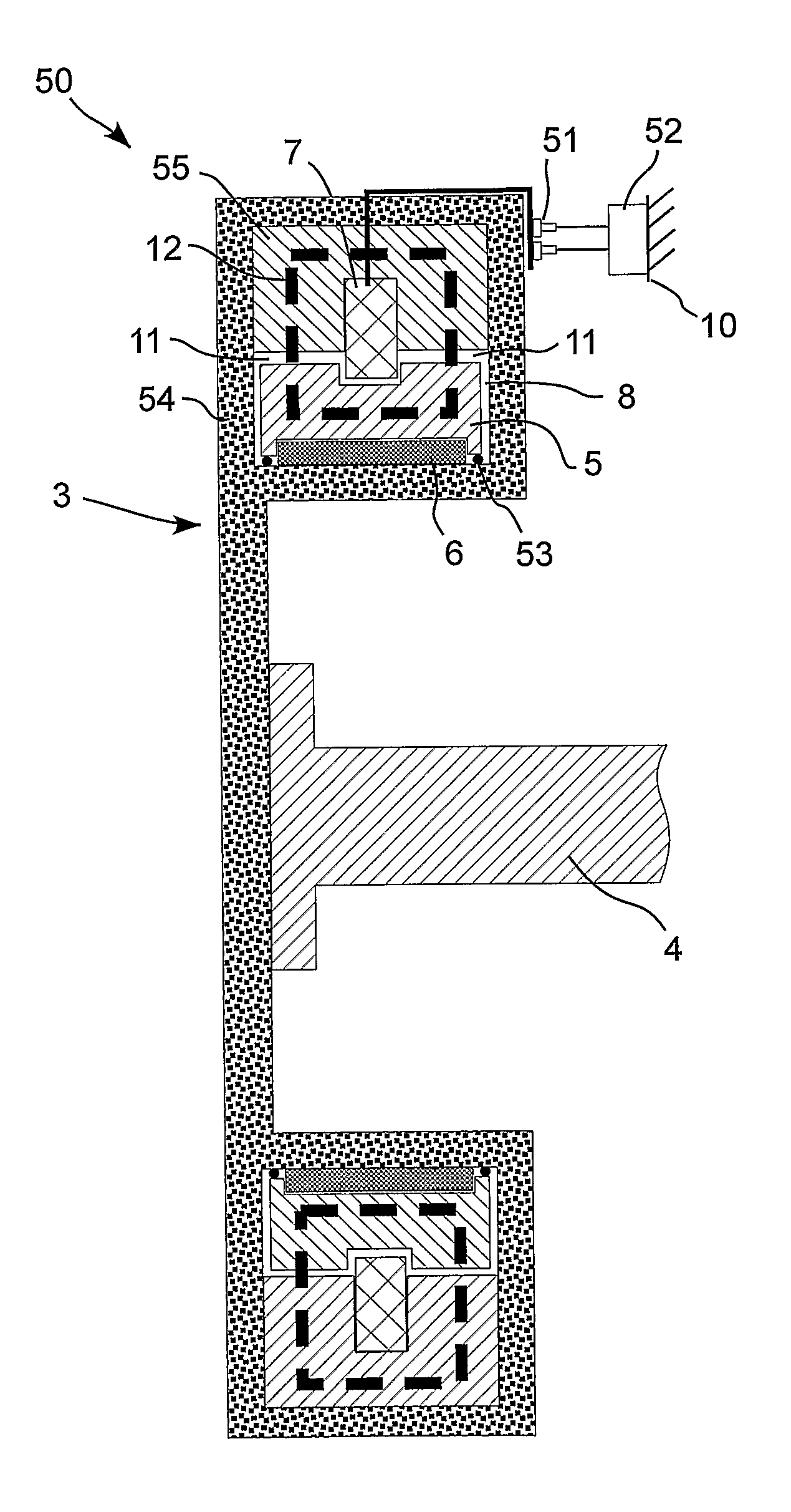
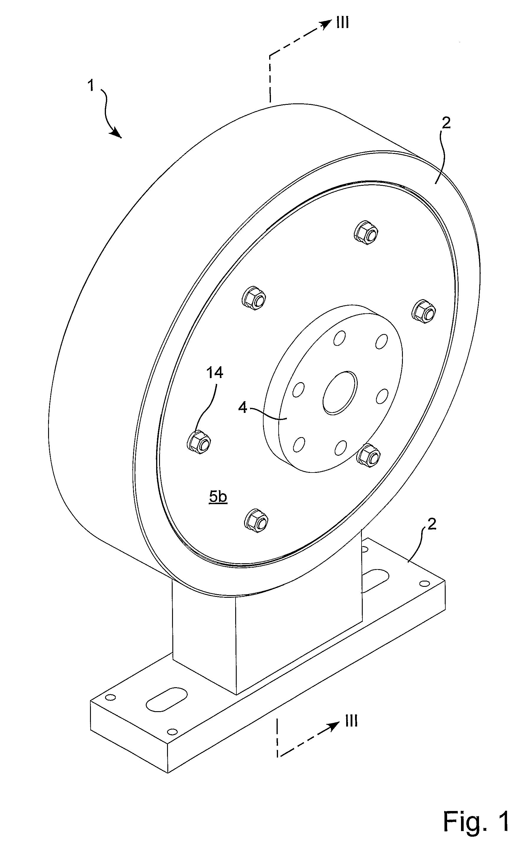
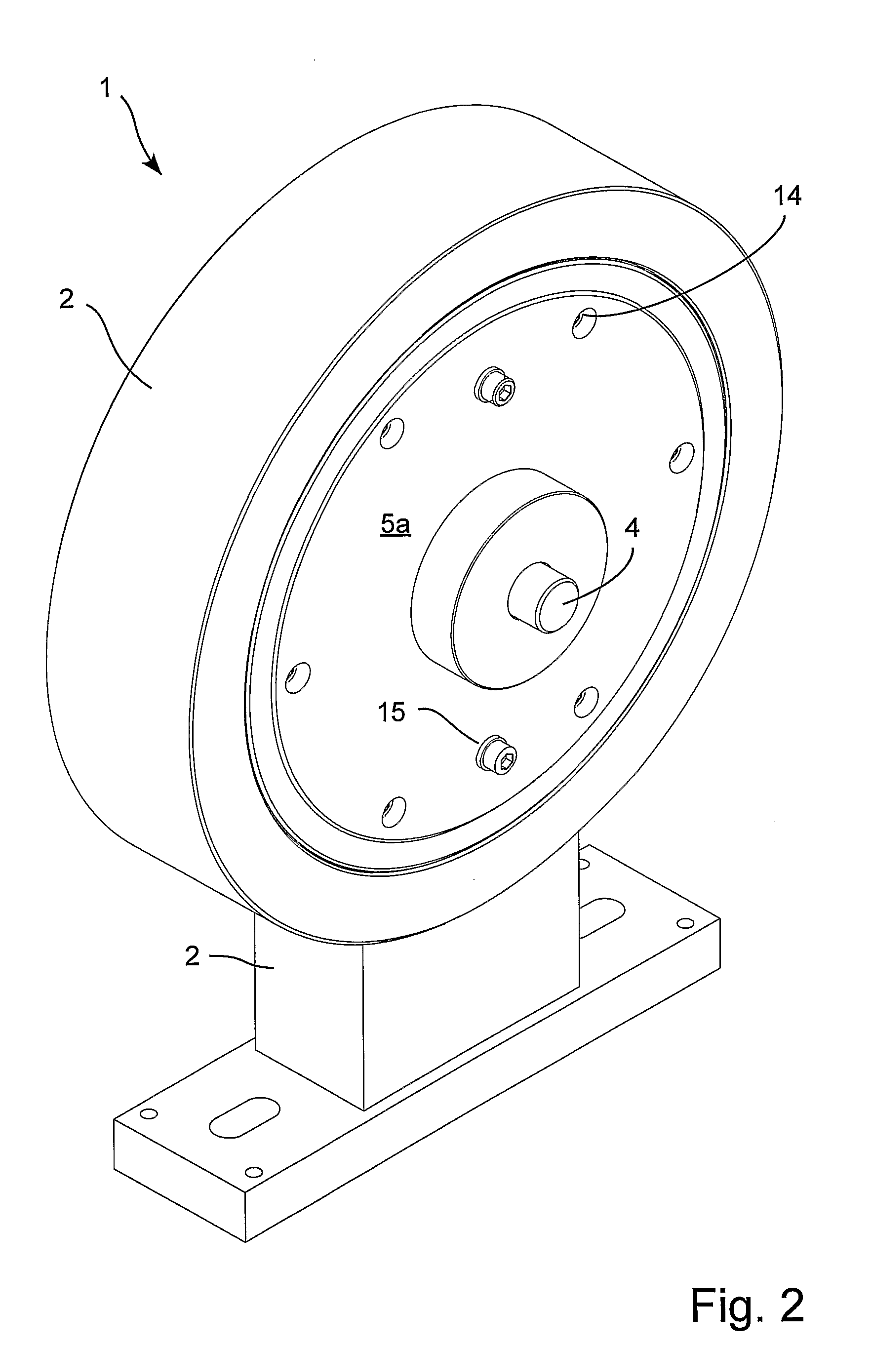
[0033]The first embodiment 1 of a torsional vibration damper shown in FIGS. 1-3 comprises a housing 2, an actuation element 3 fixedly mounted on a drive shaft 4, an inertia element 5 (5a,5b) rotatably mounted on the drive shaft 4 via a bearing 6, and a coil 7 fixedly attached to the housing 2 acting as a magnetic field generator. An enclosed volume 8 is arranged between the actuation element 3 and the inertia element 5. Furthermore, the enclosed volume 8 is filled with a small amount of Magneto-Rheological (MR) fluid 9.

[0034]As can be seen from FIGS. 1 and 2, the housing 2, the coil 7, the actuation element 3 and the inertia element 5 are all essentially circular. Furthermore, the housing 2 with the coil 7, the actuation element 3, and the inertia element 5 are all co-axial and are all rotatable with respect to each other. The housing 2 with the coil 7 is however fixedly attached to a fixed surface 10. Since the coil 7 is stationary with respect to the fixed surface 10, the power su...


PUM


Abstract

Torsional vibration damper which is suitable for dampening the motion of a rotatable element, said torsional vibration damper comprising an ‘actuation’ element which is connectable to the rotatable element, an ‘inertia’ element arranged co-axially and rotatably with said actuation element, an enclosed volume between said inertia element and said actuation element where a cross section through said enclosed volume taken on a plane which is parallel to the axis of the actuation element comprises at least one ‘axial’ portion which is arranged essentially parallel to the axis of the actuation element, an Electro-Rheological or a Magneto-Rheological fluid arranged at least in a part of said enclosed volume, and an electric or a magnetic field generator in the form of a coil which generates an electric or a magnetic field which passes through at least a portion of said enclosed volume. The field generator is integrated into the torsional vibration damper in such a way that a majority of the magnetic or electric field lines generated by the field generator pass through said ‘axial’ portion of said enclosed volume. In this way, an effective torsional vibration damper is provided.

Description

TECHNICAL FIELD OF THE INVENTION[0001]The current disclosure relates to a torsional vibration damper which is suitable for dampening the motion of a rotatable element, said torsional vibration damper comprising an “actuation” element which is connectable to the rotatable element, an “inertia” element arranged co-axially and rotatably with said actuation element, an enclosed volume between said inertia element and said actuation element where a cross section through said enclosed volume taken on a plane which is parallel to the axis of the actuation element comprises at least one “axial” portion which is arranged essentially parallel to the axis of the actuation element, an Electro-Rheological or a Magneto-Rheological fluid arranged at least in a part of said enclosed volume, and an electric or a magnetic field generator in the form of a coil which generates an electric or a magnetic field which passes through at least a portion of said enclosed volume.[0002]Please note that for the ...

Claims


Application Information

Patent Timeline
Patent Type & Authority Applications(United States)
IPC IPC(8): F16F9/53
CPCF16F15/1485F16F9/53
Inventor KLIT, PETERSANTOS, ILMAR FERREIRANISSEN, RASMUS THRANBERGHANSEN, HENRIK BALDUR NORREGARD-HANSEN
Owner DTU
Why Eureka
Try Eureka