Scalable immersed-filtration method and apparatus

a filtration method and immersion technology, applied in the field of filtration systems, can solve the problems of frequent and costly upkeep, affecting aquatic life negatively, and prone to blockage, so as to reduce the potential for preferential flow, easy to scale up or integrate, and easy to scale up

Inactive Publication Date: 2009-07-23
ZAITER SOHAIL
View PDF45 Cites 20 Cited by
  • Summary
  • Abstract
  • Description
  • Claims
  • Application Information

AI Technical Summary

Benefits of technology

[0011]The present invention provides a method and apparatus for filtering a large volume fluid intake system using a modular immersion filtration array that can be easily scaled for use in a wide variety of immersion filtering applications. The immersed-filtration array is composed of a plurality of individual filtration modules. Each filtration module has a mating end that allows the module to be coupled with a base unit or plenum via a common interface port located on the base unit. The array can be scaled in a plurality of ways. For example, the number of common interface ports on the plenum or base unit can be increased to allow a corresponding increase in the number of filtration modules. In another embodiment, the number and configuration of base units can be increased to allow increases in flow-through and filtration capacity that varies with the number of filtration modules per plenum.
[0013]The filter stack is sandwiched between a first end and a second end of the stacking core. The first end comprises an outer circumference and bottom side which form a mating surface to couple the filtration module to a common interface port of a plenum. An abutment side of the first end forms a base against which the filter stack abuts. The interior of the first end is hollow and the top side contains a plurality of cavities. In the column of stacked filter elements disposed on the stacking core, the plurality of integral fluid channels accommodate the flow of filtrate from the filter stack, through the cavities in the top side of the first end of the stacking core, and out the bottom side of the first end of the stacking core, thereby allowing the filtrate to traverse the plenum to which the filtration module is attached and moving the filtrate into the general fluid intake system. The second end of the stacking core is affixed with an adjustable compression means that provides counter-pressure to hold the filter stack against the top side of the first end of the stacking core.
[0014]The adjustable compression means allows the filter stack to be backwashed by reversing the flow of fluid through the filter stack. The pressure generated by this counter flow reduces the pressure applied to the filter stack by the compression means, thereby allowing the filter elements within the stack to separate as fluid flows from the interior to the exterior of the stack, removing any impinged material from the outside of the stack in the process. The stacking core is rigid enough to withstand high radial forces and the integral passages reduce the potential for preferential flow of backwash fluid. Avoidance of preferential flow is a significant feature that ensures uniformity of flow of backwash fluid throughout the filter elements in the stack, which ensures even cleaning of the individual filter elements in the filter stack.
[0015]An advantage of the filtration module of the present invention is its modular design, which allows it to be incorporated into any conceivable two or three dimensional configuration that could be designed for a fluid intake system. Additionally, this modular design allows the present invention to be easily scaled up or down to suit essentially any large volume fluid processing system. Yet another advantage of the modular, scalable nature of the present invention is that it can be easily incorporated into a wide variety of different filtration array architectures to accommodate almost any imaginable physical location of a fluid intake system.
[0016]Another advantage of the filtration module of the present invention is a high ratio of surface area to three dimensional volume, which allows a robust level of fluid processing capacity at a low velocity of fluid intake (Vi). This is advantageous in the context of an immersed-filtration array incorporating the present invention because it reduces ichthyoplankton entrainment / impingement rates by maintaining a favorable ratio of Vw to Vi, thereby reducing the probability of ichthyoplankton proximity to the point of intake.
[0017]Advantageously, the filtration module of the present invention virtually eliminates ichthyoplankton entrainment rates because the filter element grooves are sized in the micron range, while the lower limit of ichthyoplankton diameter is about 0.5 mm.

Problems solved by technology

Unfortunately, according to U.S. Environmental Protection Agency (EPA) estimates, these fluid intake systems remove billions of aquatic organisms from the water bodies in which they are used, including fish, crustaceans, shellfish, sea turtles, marine mammals, as well as a plethora of other aquatic life forms.
Fluid intake systems negatively impact aquatic life in two major ways: entrainment and impingement.
Disadvantageously, these systems are prone to clogging, and require frequent and costly upkeep to maintain their intake function.
Disadvantageously, this system is labor intensive and costly to install, as well as difficult to maintain.
However, the filter cartridge of the '454 patent was not heretofore used in such a fluid intake filtering application.
On the contrary, the filter cartridge of the '454 patent was designed as an in-line filter for use in high pressure applications; consequently, it has aspects that are not suited for use in screening large volume fluid intake systems.
Additionally, because of the high pressures involved in this filtering application (and correspondingly high values of Vi), the mounting flanges contain narrow diameter fluid connectors for moving the filtrate between the two chambers of the vessel (FIG. 1, 26), and such connectors would not be suitable for an application using lower values of Vi (e.g. cooling water intake for a power plant).

Method used


Image

  • Scalable immersed-filtration method and apparatus
  • Scalable immersed-filtration method and apparatus
  • Scalable immersed-filtration method and apparatus

Examples


Embodiment Construction

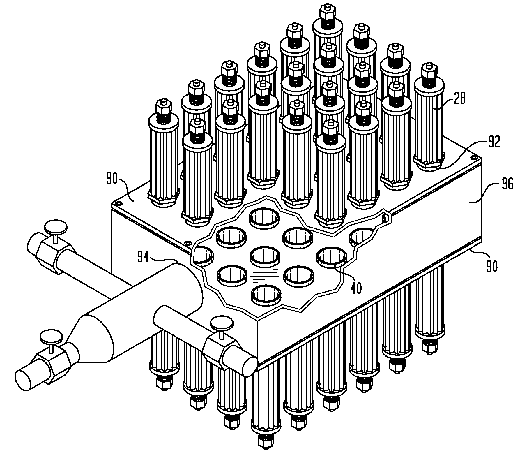
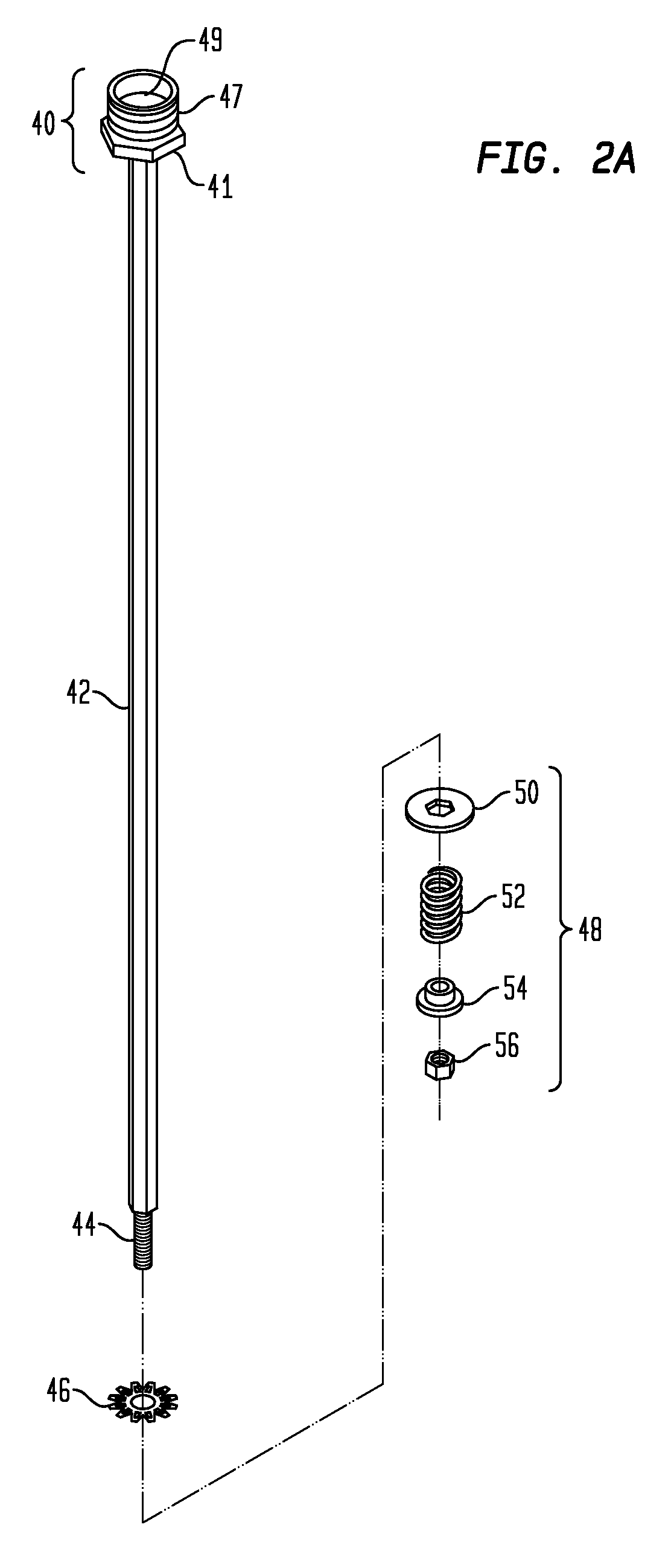
[0029]As illustrated in FIGS. 2-5, an immersed-filtration apparatus according to the invention is comprised of at least one filtration module, which in turn is comprised of a plurality of stacked filter elements. As generally illustrated in FIG. 2A, the filtration module is comprised of a geometric stacking core (42), which holds a plurality of filter elements (46) to form the filter stack (FIG. 3, 62). The stacking core (FIG. 4A, 42) has a geometric shape that corresponds to the inner cavity of the filter element (FIG. 4B, 70), a mating end (FIG. 2A, 40) comprising a mating surface (FIG. 2A, 47) and a conduit for filtrate outflow (FIG. 2A, 49), and a second end comprising an attachment means (44) for affixing a compression means (48).

[0030]As depicted in FIG. 4B, the filter elements are 1½″ wide and generally constructed and configured as described in the '454 patent, consisting of an outer filtration portion (72) and an inner geometrically shaped cavity (70) connected to one anoth...


PUM

PropertyMeasurementUnit
pore sizeaaaaaaaaaa
diameteraaaaaaaaaa
diameteraaaaaaaaaa

Abstract

A method and apparatus for filtering a large volume fluid intake system using a modular immersed-filtration array that can be easily scaled for use in a wide variety of immersion filtering applications. The immersed-filtration array is composed of a plurality of individual filtration modules. Each filtration module has a mating end that allows the module to be coupled with a base unit or plenum via a common interface port located on the base unit. The array can be scaled in a plurality of ways.

Description

FIELD OF THE INVENTION[0001]The present invention relates to filtration systems, and more particularly to filtration systems at a large volume of fluid intake.BACKGROUND OF THE INVENTION[0002]Large volume fluid intake systems are used for generating hydroelectric power, providing cooling water for manufacturing and power generation plants, providing irrigation and potable water supplies, and providing source water for desalinization plants. In the U.S. alone, these systems take in more than 200 billion gallons of fluid per day. Unfortunately, according to U.S. Environmental Protection Agency (EPA) estimates, these fluid intake systems remove billions of aquatic organisms from the water bodies in which they are used, including fish, crustaceans, shellfish, sea turtles, marine mammals, as well as a plethora of other aquatic life forms.[0003]Eggs and larvae of fish (commonly referred to as ichthyoplankton) are particularly sensitive to large volume fluid intake systems because they hav...

Claims


Application Information

Patent Timeline
Patent Type & Authority Applications(United States)
IPC IPC(8): E02B9/02
CPCB01D29/114B01D29/46B01D29/52B01D29/54
Inventor ZAITER, SOHAIL
Owner ZAITER SOHAIL
Why Eureka
Try Eureka