Determining Orientation For Seafloor Electromagnetic Receivers

a technology of electromagnetic receivers and orientation, applied in the direction of electromagnetic wave detection, instruments, specific gravity measurement, etc., can solve the problems of insufficient accuracy of attitude sensor mounted on the receiver frame, inability to accurately determine the orientation of the receiver, and low accuracy of the receiver azimuth provided by this method

Inactive Publication Date: 2009-07-23
EXXONMOBIL UPSTREAM RES CO
View PDF10 Cites 33 Cited by
  • Summary
  • Abstract
  • Description
  • Claims
  • Application Information

AI Technical Summary

Problems solved by technology

Inaccurate receiver orientations can have significant effects on the decomposed components.
Thus, because CSEM receiver arms need to be flexible, an attitude sensor mounted on the receiver frame is insufficient for determining accurate orientations of the dipole axes.
Receiver azimuth accuracy provided by this method is not very high.
Unfortunately the cross-line component is highly sensitive to small orientation errors.
It could be significantly worse using a vessel without dynamic positioning in rough weather conditions, where the source may not be towed directly over the receiver (inducing either an across-line offset or a yaw between the source transmitter and the sail line).
Thus, widely used methods focus on the receiver azimuth (α′), but do not appear to disclose how to determine receiver orientations uniquely, i.e. both the azimuth (α) and the tilts (β and γ) of the two horizontal channels.
1) Data interpretation is mainly focused on the inline electric component, which is normally not significantly affected by the tilt angles if the seafloor topography is minimal;
2) The vertical electric component is not measured or not fully utilized in data interpretation; and
3) No reliable and accurate data driven method is available to determine the receiver orientations.

Method used


Image

  • Determining Orientation For Seafloor Electromagnetic Receivers
  • Determining Orientation For Seafloor Electromagnetic Receivers
  • Determining Orientation For Seafloor Electromagnetic Receivers

Examples


Embodiment Construction

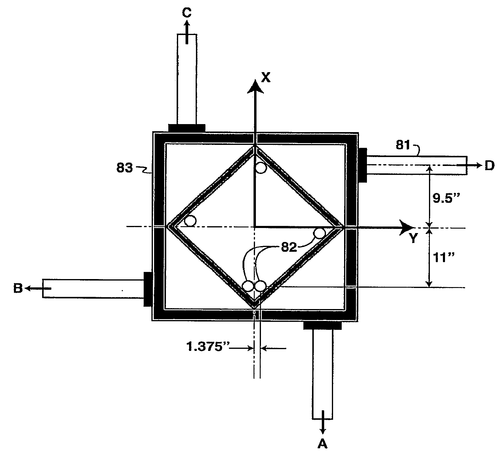
[0051]The present invention uses the EM receiver frame as a local body reference; the three-dimensional orientation of a dipole is estimated relative to the EM receiver frame. The EM receiver frame must be equipped with a suitable attitude sensor (α′, β′ and γ′) and all local body offsets (dimensions between sensors, mounting points and the like) must be precisely known (preferably to within 1 mm precision) in order to perform the trigonometric calculations needed to solve for the dipole orientation angles from the measured quantities. A vertical cross section of an EM receiver frame 71 is shown in FIG. 7, with acoustic transducer locations 72 suitable for the acoustic ranging (LBL) embodiments of the present invention. An upper part of the frame 73 is called the bale and typically is made of stainless steel. The “flag pole”74 provides a location for an out-of-plane sensor needed for range intersection embodiments of the invention. Actually, the sort of pole used in current receiver...


PUM


Abstract

Apparatus and method for estimating the 3D orientation angles for remotely deployed devices with flexible arms such as dipole antennas of receivers used in marine controlled-source electromagnetic surveys to explore for hydrocarbons. Acoustic transponders or transducers, or other positioning sensors such as attitude sensors or strain-sensitive fiber optic cables are placed on each electrode arm of the receiver. Acoustic sensors (101) on the receiver frame (94) work in conjunction with the positioning sensor(s) (101) on the electrode arms (92) to provide accurate 3D spatial position of the receiver electrodes (93) relative to the receiver frame. Alternatively, sonar transducers mounted on the frame are used to image the electrode arms, which image can be enhanced by fixing reflectors to the arms. An attitude sensor is mounted on the receiver frame, enabling conversion of the relative electrode positions to an earth reference frame.

Description

[0001]This application claims the benefit of U.S. Provisional Application No. 60 / 801,888 filed on May 19,2006.FIELD OF THE INVENTION[0002]This invention relates generally to the field of geophysical prospecting and reservoir delineation, and more particularly to electromagnetic prospecting. Specifically, the invention is a method for determining receiver orientations in electromagnetic surveys of subsurface regions where the receivers cannot be located by hand or be directly measured for orientation, such as ocean-bottom receivers in surveys of regions below the ocean bottom. Adaptation of the invention to other applications such as ocean-bottom seismic data acquisition will be obvious to practitioners in the field.BACKGROUND OF THE INVENTION[0003]The marine CSEM (Controlled Source Electromagnetic) exploration method uses a man-made source to generate Electromagnetic (EM) waves and deploys receivers on the seafloor (if the survey is in a marine environment) to record EM signals. The...

Claims


Application Information

Patent Timeline
Patent Type & Authority Applications(United States)
IPC IPC(8): G01V3/12G02B6/00G01B17/00G01S15/00
CPCG01V3/12G01V3/083
Inventor SUMMERFIELD, PHILIP J.PHILLIPS, TOM C.
Owner EXXONMOBIL UPSTREAM RES CO
Why Eureka
Try Eureka