Structural feed aperture for space based phased array antennas

a phased array, space-based technology, applied in the direction of antennas, antenna details, antenna adaptation in movable bodies, etc., can solve the problems of reducing the strength of the antenna, the weight and volume are particularly significant constraints, and the weight and volume are less than optimal, so as to reduce the net weight, cost and volume, and increase strength.

Inactive Publication Date: 2009-07-23
THE BOEING CO
View PDF2 Cites 12 Cited by
  • Summary
  • Abstract
  • Description
  • Claims
  • Application Information

AI Technical Summary

Benefits of technology

[0009]A structural phased array antenna and method for manufacturing are disclosed. An integrated structural antenna aperture can be used to reduce net weight, cost, and volume where an array of antenna elements are incorporated into a structural member, e.g. in a spacecraft. A structural material layer, such as a structural foam, may be used with an array of individual antenna element cavities machined into the layer. The antenna element cavities are lined with a conductive material, such as plated aluminum. Facesheets may be bonded to the front and / or backside of the structural material layer in order to increase strength using an RF transparent material. The array of antenna elements may be coupled to filters at the back side of structural material layer.
[0010]Embodiments of the disclosure allow for less backup structure to support the phased array. In addition, fabrication of the multiple antenna elements in the structural material layer may be machined as a group, rather than individually. This can accelerate overall production of the antenna.
[0011]Embodiments of the disclosure can provide large cost savings over the existing antenna solutions by reducing the overall mass and volume of a spacecraft. This can allow the spacecraft to be launched on a smaller, less-costly launch vehicles. Thus, the overall savings can be significant. Embodiments of the disclosure can enable the design, manufacturing, and testing of phased array antennas, particularly space-based antenna, that are cheaper, lighter, and more powerful than current antennas.
[0013]The phased array antenna may be employed such that the supporting material layer comprises a support in an underlying structure for the phased array antenna. In one example, the support in the underlying structure for the phased array antenna may be disposed on a spacecraft. The structural efficiency of the phased array yields a lower overall mass, an important consideration in spacecraft design.

Problems solved by technology

This approach can yield results that are less than optimal.
This adds extra weight, volume, and fabrication cost.
Weight and volume are particularly significant constraints in the design of antenna on spacecraft.
In addition, the installation of individual horns or antenna elements adds complexity to the dimensional stack up and flow time assembly.

Method used


Image

  • Structural feed aperture for space based phased array antennas
  • Structural feed aperture for space based phased array antennas
  • Structural feed aperture for space based phased array antennas

Examples


Embodiment Construction

[0027]1. Overview

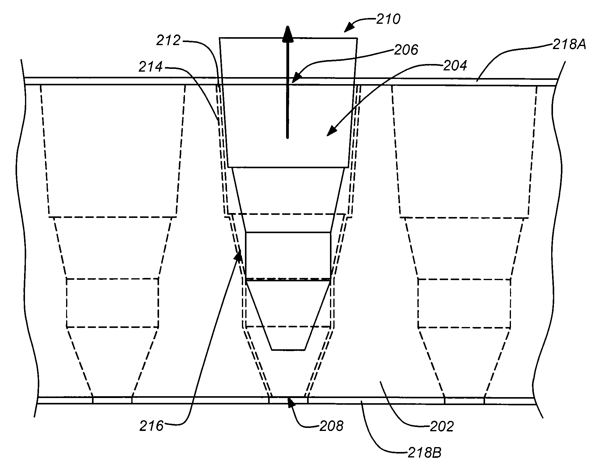
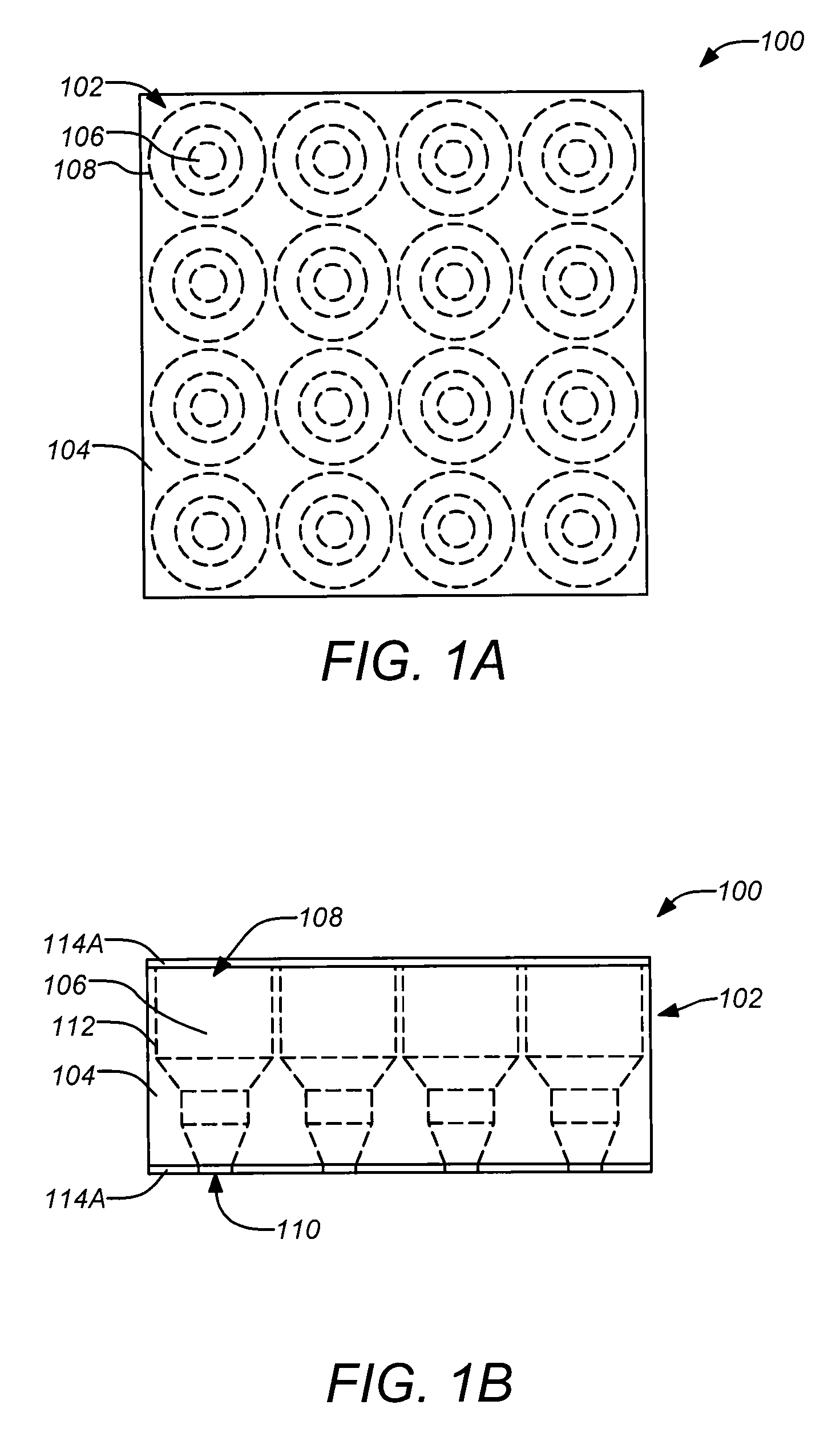
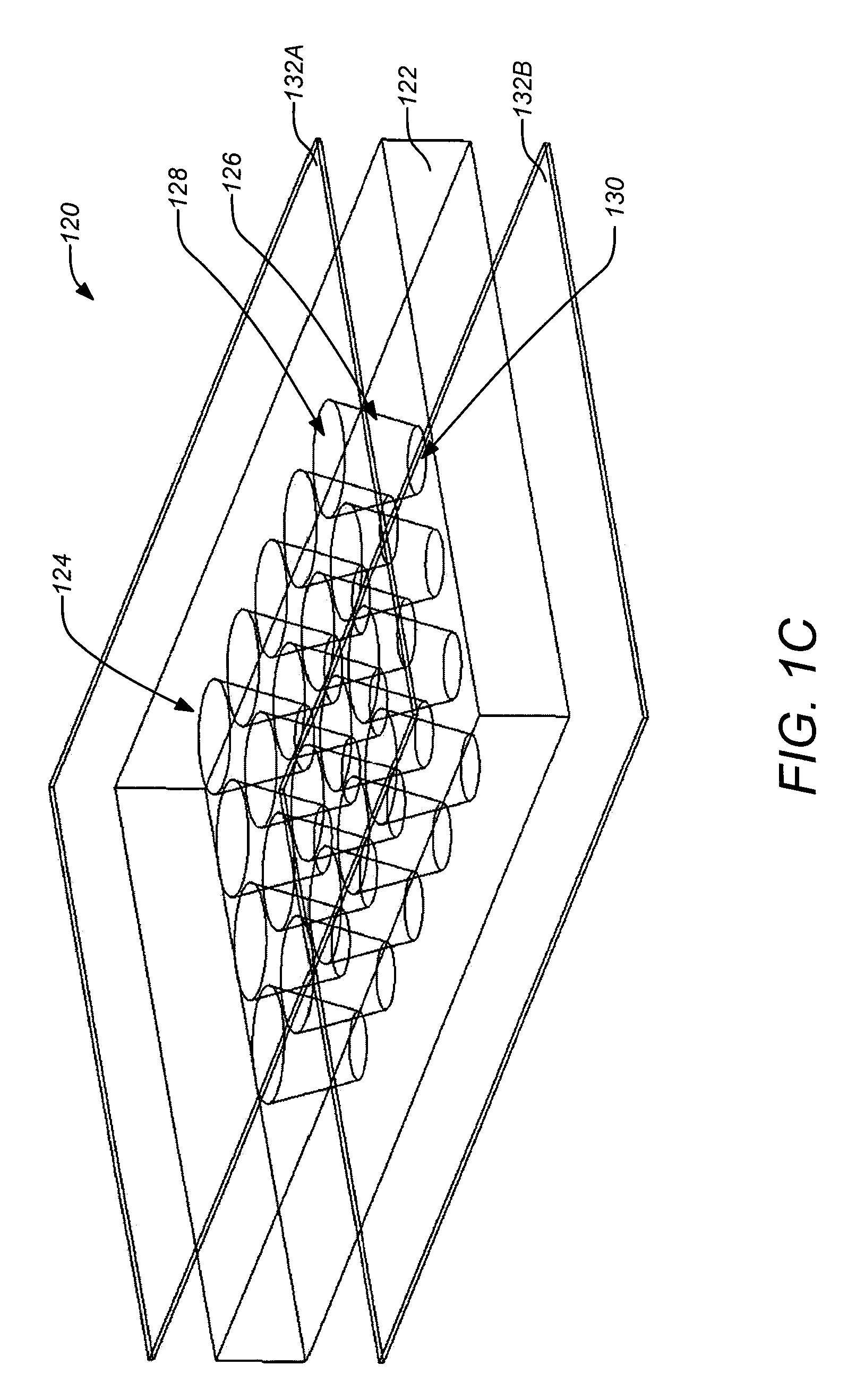
[0028]As previously mentioned, embodiments of the disclosure are directed to structural phased array antennas and methods for their manufacturing. An array of antenna elements can be incorporated into a structural member of a spacecraft where a structural material layer, such as a structural foam, has an array of individual antenna element cavities machined into the layer. The antenna element cavities are lined with a conductive material, such as plated aluminum. Facesheets may also be bonded to the front and / or backside of the structural material layer in order to increase strength and / or stiffness using an RF transparent material. The array of antenna elements may be coupled to filters at the back side of structural material layer that lead to the remainder of the communications signal electronics.

[0029]Embodiments of the disclosure allow for less backup structure to support the phased array, thus reducing the weight, cost, and volume. Embodiments of the disclosur...


PUM

PropertyMeasurementUnit
thicknessaaaaaaaaaa
tensile strengthaaaaaaaaaa

Abstract

A structural phased array antenna and method for manufacturing are disclosed. An integrated structural antenna aperture can be used to reduce net weight, cost, and volume where an array of antenna elements are incorporated into a structural member, e.g. in a spacecraft. A structural material layer, such as a structural foam, may be used with the array of individual antenna element cavities machined into the layer. The antenna element cavities are lined with a conductive material, such as plated aluminum. Facesheets may be bonded to the front and / or backside of the structural material layer in order to increase strength and / or stiffness using an RF transparent material. The array of antenna elements may be coupled to filters at the back side of structural material layer.

Description

BACKGROUND[0001]1. Technical Field[0002]This disclosure relates to antenna system. Particularly, this disclosure relates to phased array antenna systems.[0003]2. Description of the Related Art[0004]An essential component of any wireless communications system is the antenna that transmits and / or receives the electromagnetic signals. One conventional antenna structure, often employed in communications satellites, includes a reflector that has received or transmitted signals “reflected” off it and focused to be collected in one or more feed horns. The reflector and feed horn configuration is typically manipulated to direct or “point” the coverage area of such an antenna. Newer antenna systems may employ phased arrays where an array of discrete antenna elements are used in combination to transmit or receive the desired electromagnetic signal. Such phased array systems can dispense with much of the pointing manipulation typically required with conventional reflectors because the output o...

Claims


Application Information

Patent Timeline
Patent Type & Authority Applications(United States)
IPC IPC(8): H01Q1/28H01Q3/26H01P11/00
CPCH01Q1/288Y10T29/49016H01Q21/064H01Q13/0283
Inventor BULLOCK, STEVEN J.GRIESS, KENNETH H.KLEIN, III, THOMAS F.LAYTON, OTIS F.NAVARRO, JULIO A.URCIA, MANNY S.
Owner THE BOEING CO
Why Eureka
Try Eureka