Image display device and its manufacturing method

a technology of image display device and manufacturing method, which is applied in the manufacture of electric discharge tubes/lamps, identification means, instruments, etc., can solve the problems of difficulty in visibility, deterioration of image appearance quality, and low reliability of image display units, and achieve high reliability. the effect of image display units

Active Publication Date: 2009-07-23
DEXERIALS CORP
View PDF3 Cites 59 Cited by
  • Summary
  • Abstract
  • Description
  • Claims
  • Application Information

AI Technical Summary

Benefits of technology

[0011]According to the present invention, it is possible to manufacture a highly reliable image display device in which the cure of the resin can proceed sufficiently also in the

Problems solved by technology

When such a structure has been adopted, however, the presence of the air-space induces scattering of light to decrease the contrast or luminance, thereby entailing a problem of deteriorating an image appearance quality.
In the structure, since the protective pan

Method used


Image

  • Image display device and its manufacturing method
  • Image display device and its manufacturing method
  • Image display device and its manufacturing method

Examples


examples

[0062]Next, concrete examples of the present invention will be described based on experimental results.

[0063]Preparation of a Resin Composition to be Light-Cured and Thermally Cured:

[0064]Seventy parts by weight of an esterification product of a polyisoprene polymer added with a maleic anhydride adduct and 2-hydroxyethyl methacrelate, 30 parts by weight of dicyclopentenyl oxyethyl methacrylate, 10 parts by weight of 2-hydroxybutyl methacrylate, 30 parts by weight of hydrogenated terpene resin, 140 parts by weight of a butadiene polymer, 4 parts by weight of a photopolymerization initiator, 0.5 part by weight of a photopolymerization initiator for use in a visible light region and 10 parts by weight of a thermal polymerization initiator (organic peroxide) (produced by Nippon Oils & Fats Corporation under trade name PERBUTYL O) were kneaded with a kneading machine to prepare a resin composition. The rate of shrinkage of the resin composition by cure was 1.8%, and the storage elastic m...


PUM

PropertyMeasurementUnit
Temperatureaaaaaaaaaa
Fractionaaaaaaaaaa
Shrinkageaaaaaaaaaa

Abstract

It is possible to manufacture a highly reliable image display device capable of proceeding with resin cure even in the case where a protective panel is provided with a light shielding portion.
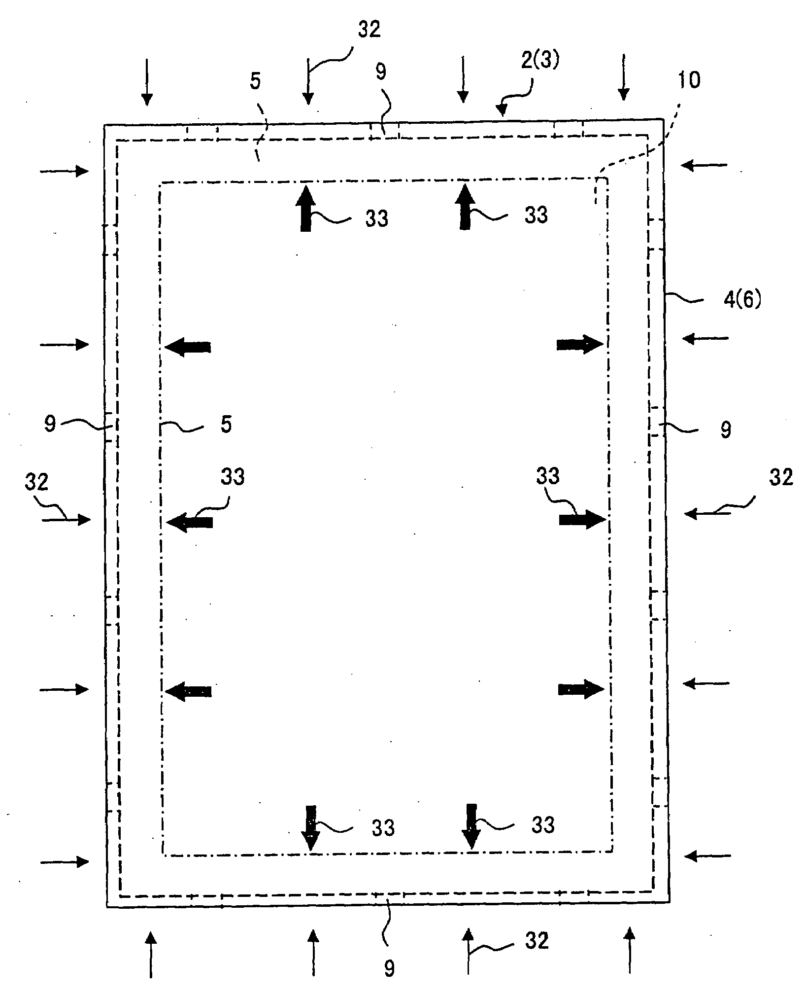
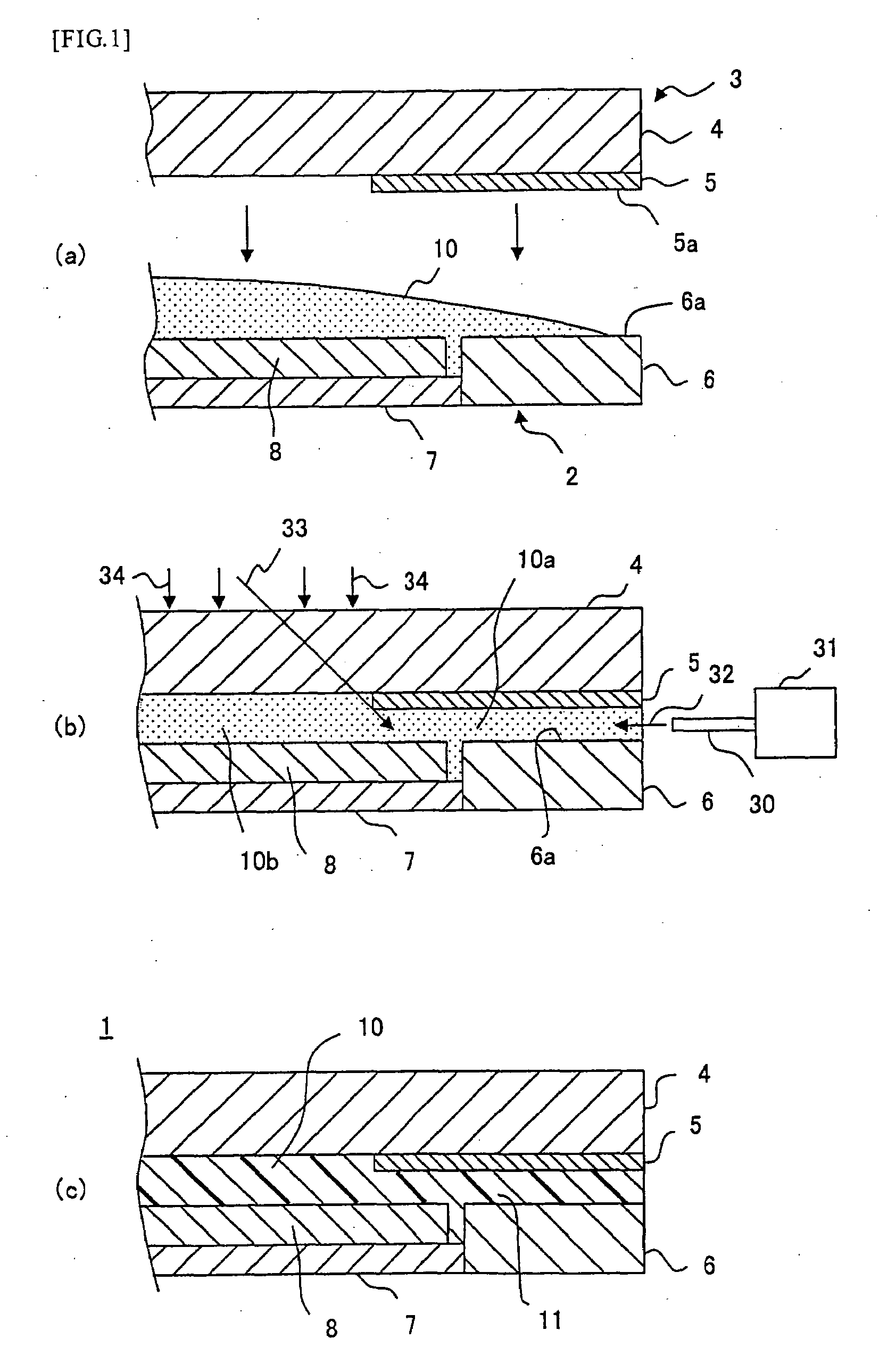
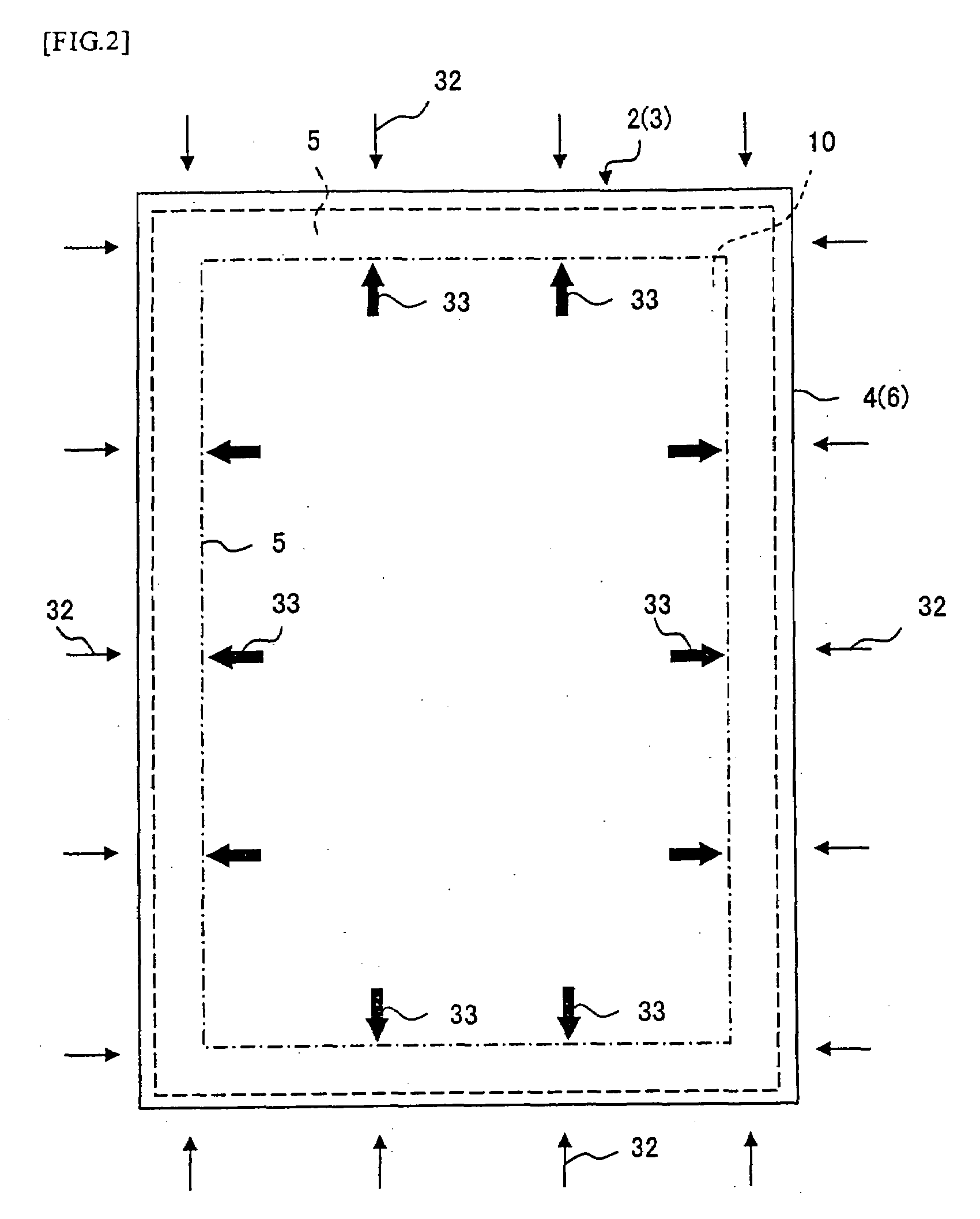
A liquid crystal display unit 2 having a liquid crystal display panel 8 and a light transmissive protective panel 3 having a light shielding portion 5 are disposed face to face, a resin composition 10 is interposed between the liquid crystal display unit and the protective panel, and the resin composition is cured into a cured resin layer 11. As the resin composition 10, a light-heat-curing resin composition and containing a photopolymerization initiator and organic peroxide of thermal polymerization initiator is used. In curing the resin composition 10, cure by light (ultraviolet rays) irradiation is performed until a cure ratio of the resin composition becomes 30% or more and thereafter thermal cure is performed.

Description

FIELD OF THE INVENTION[0001]The present invention relates to a method for manufacturing image display devices, such as a liquid crystal display (LCD) used for a mobile telephone, for example, and particularly to an improvement in a method for curing a resin composition filled between the device and a protective panel having a light shielding portion.DESCRIPTION OF THE PRIOR ART[0002]In an image display device, such as a liquid crystal display, in order to prevent impair of an image display panel or protect the surface thereof, a protective panel has been fixed on the front surface of the image display panel. For example, a transparent protective panel, such as a glass panel or a plastic panel, has been incorporated into a box body, with a slight airspace formed between itself and the image display panel via an intervening spacer disposed on the outer periphery of the image display panel.[0003]When such a structure has been adopted, however, the presence of the air-space induces scat...

Claims


Application Information

Patent Timeline
IPC IPC(8): H01J9/20
CPCG02F1/133502G02F2201/50G02F2202/28G02F2202/025G02F2201/503G02F1/133308G02F2202/023Y10T428/24355Y10T156/11Y10T156/1184G02F1/133311G02F1/133331G02F1/1333G09F9/00
Inventor SHINYA, YOSHIHISAKAMIYA, KENJIKAMATA, YUSUKE
Owner DEXERIALS CORP
Why Eureka
Try Eureka