Nasogastric tube placement and monitoring system

a monitoring system and nasogastric tube technology, applied in the field of nasogastric tube placement and monitoring system, can solve the problems of increasing the number of health problems of patients, difficult for clinicians to ensure proper placement of nasogastric tube, and the seriousness of aspiration by proxy, so as to increase the efficiency of staff.

Inactive Publication Date: 2009-07-23
NG ET OPTIMIZER
View PDF0 Cites 34 Cited by
  • Summary
  • Abstract
  • Description
  • Claims
  • Application Information

AI Technical Summary

Benefits of technology

[0024]A further object of the present invention is to provide a nasogast

Problems solved by technology

Although nasogastric intubation is a widely used, standard technique in hospitals, long term care facilities, hospices, and in-home health care delivery, it continues to be challenging for clinicians to assure proper placement of a nasogastric tube.
Inadvertent placement of a nasogastric tube has caused numerous health problems for patients.
Aspiration by proxy is a serious consequence of inadvertent misplacement.
This occurs when food or medicine is introduced by a tube that is incorrectly placed into the lungs, trachea, or esophagus, leading to dangerous aspirated pneumonia with its associated increased incidence of morbidity and mortality.
Improper tube placement has led to laryngeal injuries due to placement in the trachea and distal airways, when the organ of interest was the stomach.
Other related issues include hypersalivation, depressed cough reflex, and pharyngeal abnormalities.
Complications from improper tube positioning often result in extended hospital stays, or in some instances, results in death.
While radiographic confirmation does assure correct placement of a nasogastric tube, the patient is exposed to radiation, and the cost of radiographic confirmation is costly and radiographic confirmation is difficult or impossible in some situations, such as, for e

Method used


Image

  • Nasogastric tube placement and monitoring system
  • Nasogastric tube placement and monitoring system
  • Nasogastric tube placement and monitoring system

Examples


first embodiment

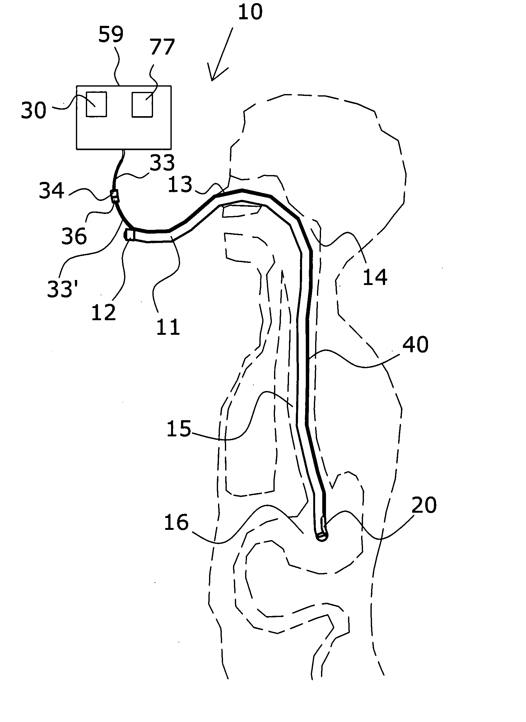
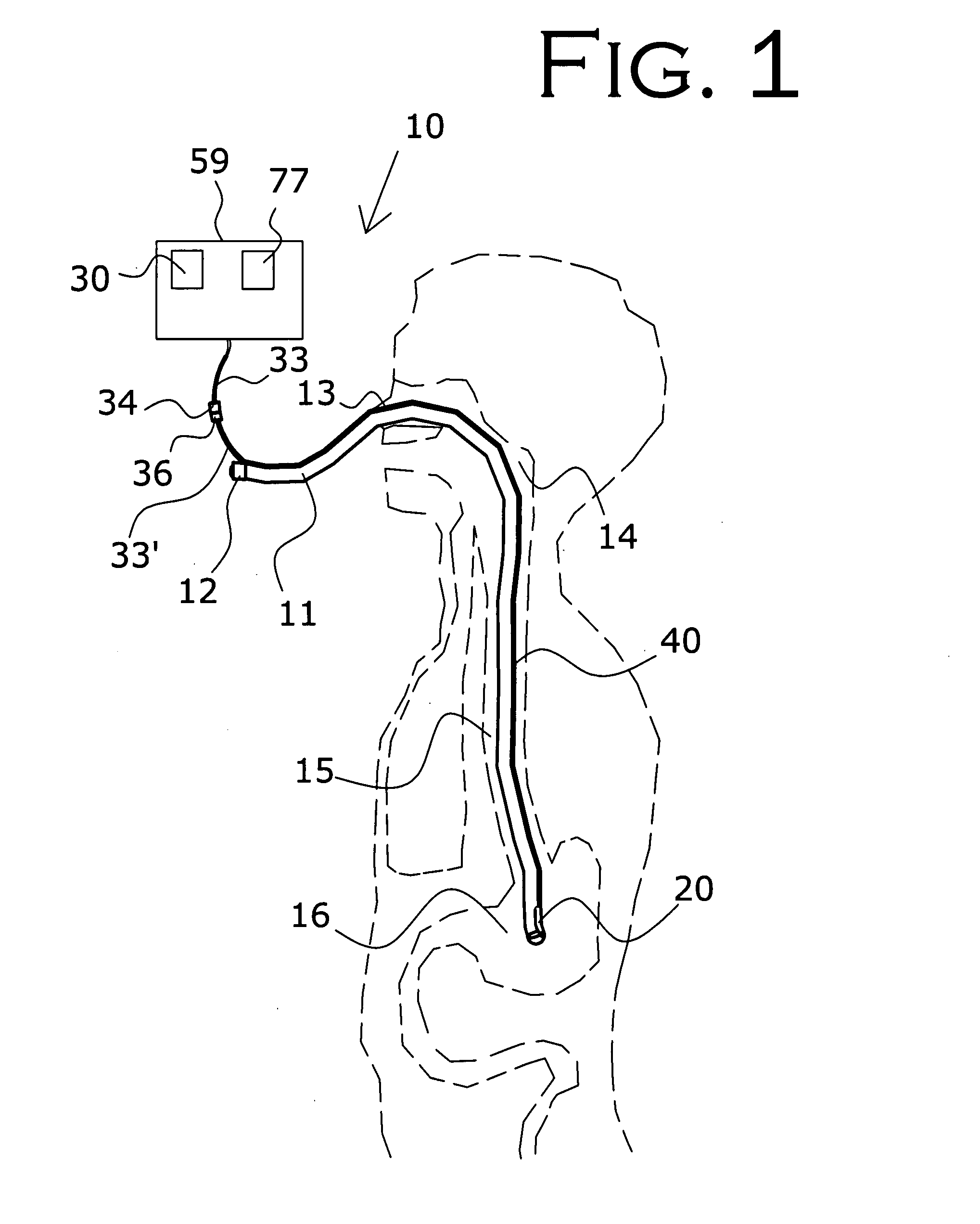
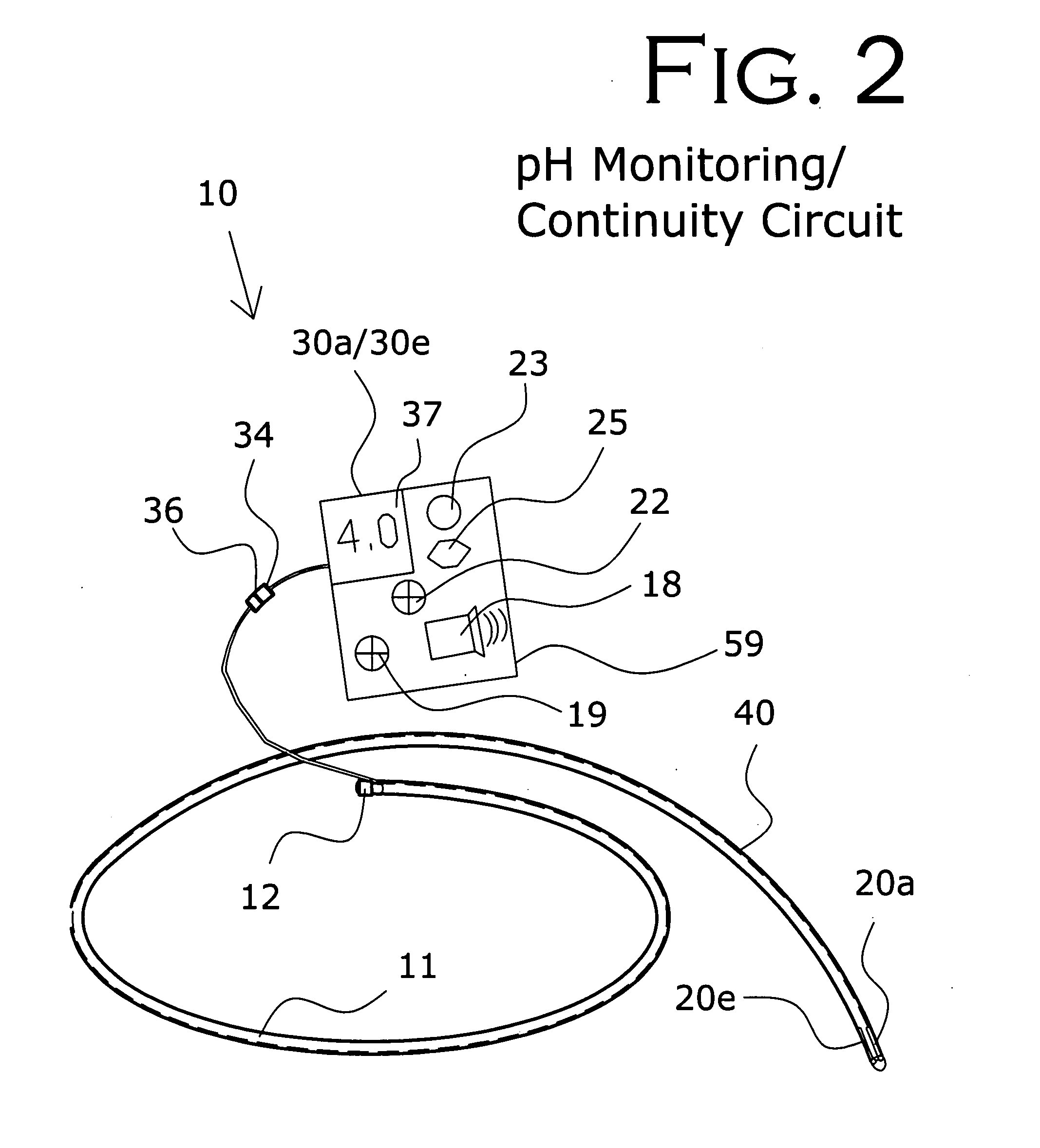
[0058]In the first embodiment, as seen in FIG. 2 and FIG. 3, a pH monitoring circuit and / or continuity circuit is provided. The feedback initiator 20 is a pH sensor 20a and / or continuity conductor 20e. PH sensor 20a continually senses the acidity or basicity of the fluid located at the distal end of flexible tube 11 by giving a measurement of the concentration of hydrogen ions. The continuity circuit, utilizing continuity conductor 20e, is a means of determining continuity through which the conductors continually monitor the conductivity of the fluid located at the distal end of the flexible tube 11, monitoring the presence of hydrogen ions.

[0059]The continuity circuit provides a potential to continuity conductor 20e at the distal end of flexible tube 11. Conducting means 40 is used as a means to provide or supply the potential to continuity conductor 20e, and, if continuity at continuity conductor 20e is available or detected, conducting means 40 further transmits the potential bac...

second embodiment

[0069]In the second embodiment, shown in FIG. 4 and FIG. 5, an audio monitoring circuit is illustrated, with the flowchart of FIG. 5 illustrating an overview of the operation of the audio monitoring circuit. The feedback initiator at the distal end of flexible tube 11 is an acoustic port 20b or opening using tube 11 as a means for sound to travel to the microphone 32 on the proximal end of tube 11, FIG. 4.

[0070]Feedback receiver 30b in the second embodiment preferably comprises a microphone 32 to receive the sounds from the distal end of flexible tube 11 configured with the appropriate amplifiers to amplify the received sounds and the appropriate circuitry to transmit the sounds via conducting means 40 to the speaker 38 which is configured with the appropriate circuitry to generate an audible sound that can be heard by the clinicians. The speaker 38 serves as a notifying device that provides the clinician with information concerning the distal end of flexible tube 11.

[0071]The sound...

third embodiment

[0072]In FIGS. 15 and 16 the third embodiment, the vibration circuit, is illustrated. A vibration vibrator 27 is provided to produce a pulsation or vibration to tube 11. The feedback initiator 20 is encapsulated beads 20y, disposed at the distal end of flexible tube 11. The encapsulated beads 20y are used to assist the clinician in determining the location of the distal end of tube 11. The encapsulated beads 20y may be any small contained objects that are space-efficient and generate an audible sound by agitation or repeated concussions. The vibration and sound from encapsulated beads 20y is received by feedback receiver 30y, the diaphragm 73 of handheld stethoscope 64, and transmitted by the stethoscope tubing to the earpieces 74. The clinician receives this sound that provides information about the distal end of flexible tube 11 via the earpieces of stethoscope 64 serving as a notifying device. Alternately, the audio monitoring circuit of FIG. 4 and FIG. 5 can be utilized with thi...


PUM


Abstract

A nasogastric tube placement and monitoring system is provided including a flexible nasogastric tube and numerous circuits that can be used alone or in combination. The circuits include a feedback initiator, a feedback receiver, and a clinician notifying device. By various means in the provided circuits, the feedback initiator provides information about the location of the distal end of the nasogastric tube. This information or data is received and analyzed by the feedback receiver that monitors the circuit, which then transmits an output to the clinician notifying device to alert or advise the attending clinician of this information. The data that is output supplies information about the location of the tube's distal end to the clinician, thereby assisting the clinician in placement of the nasogastric tube during intubation, as well as in monitoring proper tube placement after placement.

Description

CROSS-REFERENCE TO RELATED APPLICATION[0001]This application claims the benefit of co-pending U.S. Provisional Patent Application Ser. No. 60 / 797,307, filed on May 3, 2006, which is incorporated herein in its entirety.BACKGROUND OF THE INVENTION[0002]1. Field of the Invention[0003]The present invention relates generally to a medical device, a nasogastric tube for use in intubation of patients, and more particularly, to a nasogastric tube placement and monitoring system configured to assure proper placement—either in the stomach or in the lungs—and monitoring of a nasogastric tube (NG-tube) through pH / continuity, auscultatory feedback, air pressure sensors, contact pressure sensors, and indicator lights, meters, and / or speakers. A nasogastric tube is a plastic tubular conduit inserted through the nose, down through the alimentary canal into the stomach. Nasogastric tubes can also be inserted directly into the lung(s) for therapeutic purposes. Therefore the organ of interest is either...

Claims


Application Information

Patent Timeline
IPC IPC(8): A61M25/098
CPCA61M25/0105A61M2205/18A61M2205/3324A61M2210/1042A61M2205/3368A61M2205/3375A61M2205/502A61M2205/3331
Inventor ROWE, PHILIP S.
Owner NG ET OPTIMIZER
Why Eureka
Try Eureka