Ignition system

a technology of ignition system and ignition coil, which is applied in the direction of spark plugs, electric control, machines/engines, etc., can solve the problems of high secondary winding inductance, high cost, and inefficient systems

Inactive Publication Date: 2009-07-30
AMBIXTRA (PTY) LTD
View PDF14 Cites 27 Cited by
  • Summary
  • Abstract
  • Description
  • Claims
  • Application Information

AI Technical Summary

Problems solved by technology

These limitations result in a very high secondary winding inductance, which has several drawbacks including cost.
The large inductance normally requires kilometers (ten thousands of windings) of thin copper wire, which is expensive.
The systems are inefficient in that the kilometers of thin copper wire have a resistance of a few kilo-ohms.
Due to the large amount of energy that must be handled as well as the large amount of copper needed, the systems are bulky.
The energy loss due to the copper resistance, heats the transformer.
This places a severe limit on the maximum amount of energy that can be transferred to the spark and also affects the placement of the transformer for cooling.
The fuel efficiency, completeness of combustion, combustion time, exhaust cleanliness and variability in cycle-to-cycle combustion are limited.
These high voltage cables generate a large amount of electromagnetic radiation, which may influence other electronic equipment.
Because these coils are very close to the engine, normally with very little air flow around them, they overheat easily, which makes them unreliable.
The disadvantage of this approach is that the high permeability magnetic material saturates easily and that a large core is therefore required.
They all have the disadvantage that the energy must either go through the secondary winding or through a semiconductor device.
If the energy goes through the secondary winding, the transfer is very inefficient due to the high winding resistance.
These devices are expensive and also result in energy loss.
Another disadvantage of all these systems is that the self-resonance frequency of the secondary winding is low (typically less than 20 kHz).
This limits the number of successive pulses that can be generated in multiple spark ignition systems, which limits the amount of energy that can be delivered during ignition.
Even in systems where an optimal spark time is calculated (as discussed below), the spark cannot be controlled to within a few tens of microseconds.
Because of the high loss of the ignition transformer, the measurement must be done on the secondary side of the transformer, which makes the secondary side circuit complex.
Although there are a number of techniques available to measure the conditions inside the combustion chamber before ignition, none of them are widely used because they all require extra access points to the combustion chamber, are expensive, most have low reliability and are complex.
When using the spark-plug for measurements, the low secondary resonance frequency therefore limits the measuring frequency after ignition and also makes it very difficult, if not impossible, to measure gas properties before ignition.

Method used


Image

  • Ignition system
  • Ignition system
  • Ignition system

Examples


first embodiment

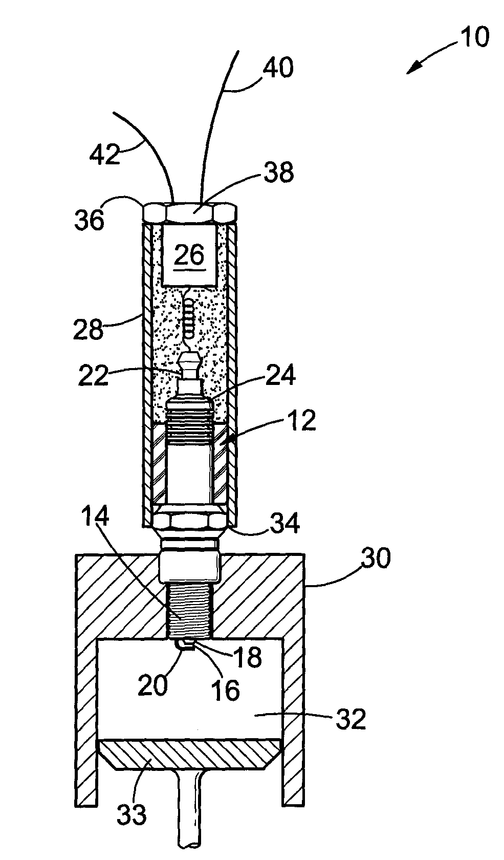
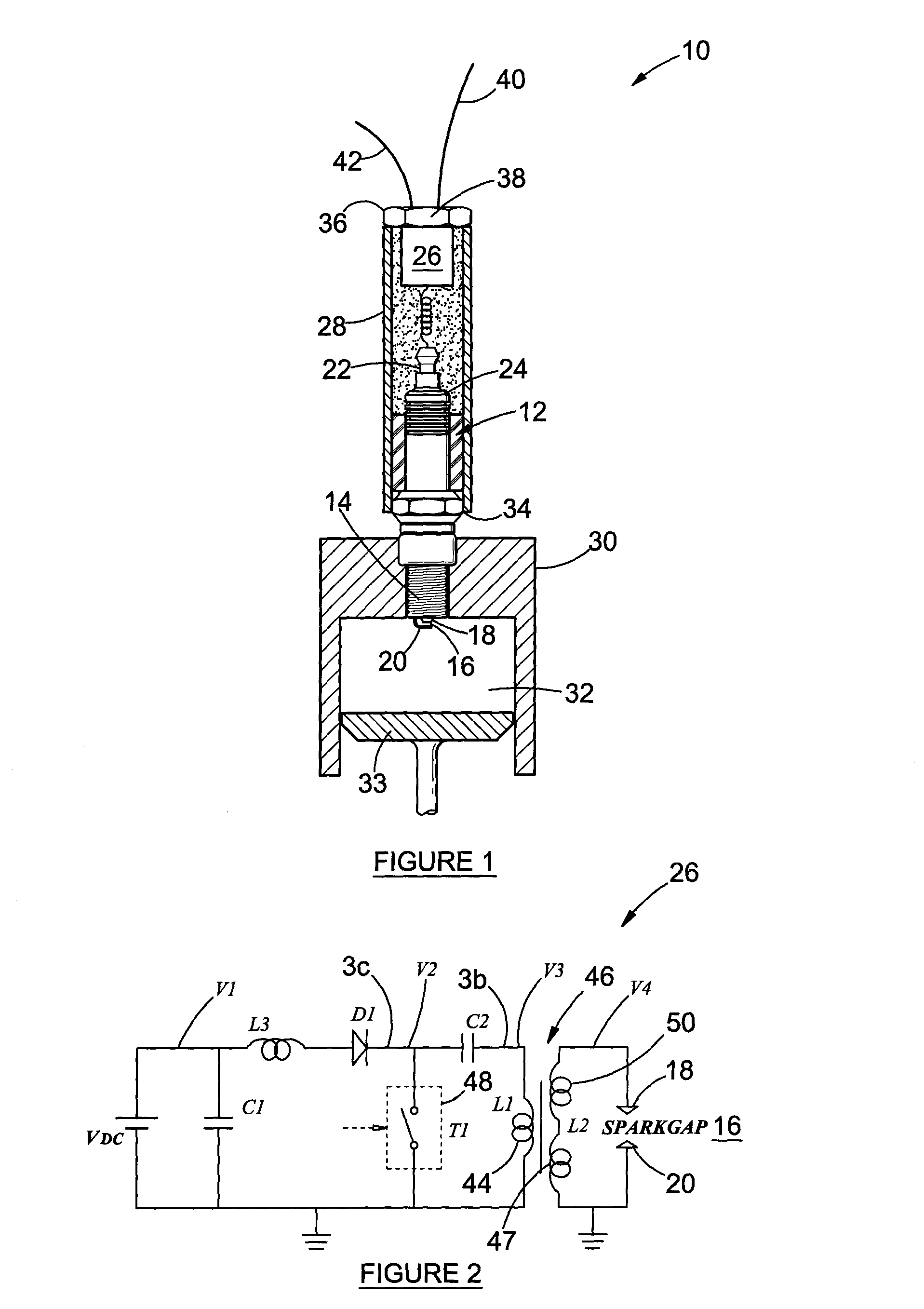
[0065]the drive circuit 26 (in the form of a capacitor discharge circuit) is shown in more detail in FIG. 2. The circuit 26 comprises a first capacitor C1 connected in series with a primary winding 44 of a local transformer 46 and a fast switching power device T1 or 48. A secondary winding 50 of the transformer is connected to the first electrode 18, which defines spark-gap 16 with grounded second electrode 20.

[0066]The power switching device 48 may comprise a power insulated gate semiconductor device, such as a MOSFET or IGBT and is preferably driven in accordance with the method of and with a drive circuit of a kind similar to that disclosed in the applicant's U.S. Pat. No. 6,870,405B1, the contents of which is incorporated herein by this reference.

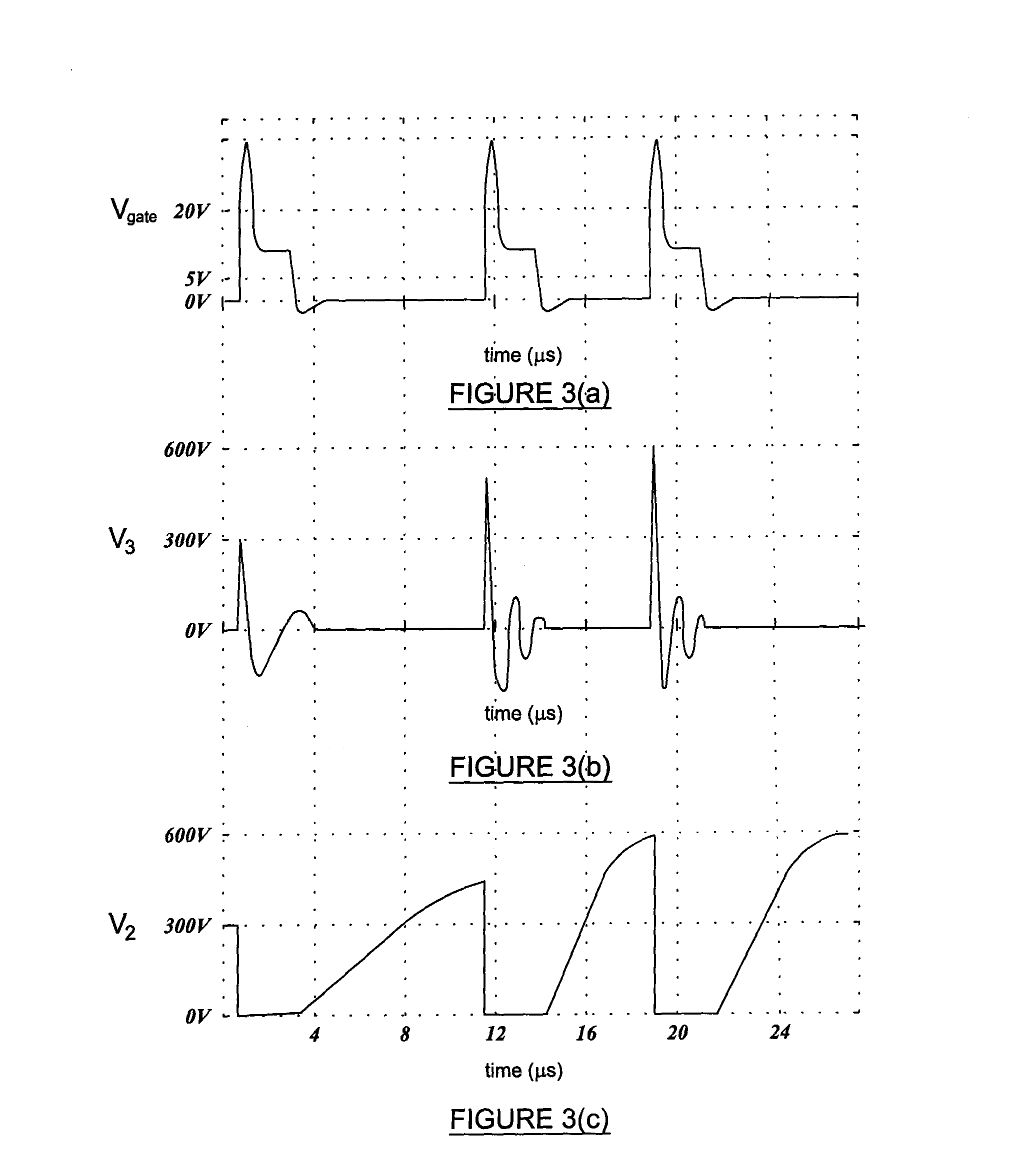
[0067]As best shown in FIGS. 2 and 6, the circuit 26 utilizes a single MOSFET 48 to generate a voltage of a few hundred volts to charge capacitor C1 as well as to switch the capacitor C1 to generate the high voltage across the gap 16. I...

second embodiment

[0078]the drive circuit 26 is shown in more detail in FIG. 9. In this embodiment, the primary winding 44 of the transformer 46 is connected to a power oscillator 56. This oscillator 56 is connected to an energy source 58, all inside the housing 28. The energy source is connectable via cable 42 to DC voltage source outside of the housing and the oscillator has a trigger input connection via cable 40 to the outside of the housing. The secondary winding 50 of the transformer 46 is weakly coupled to the primary winding 44. The secondary winding 50 is connected in series with the spark-plug 12 and the energy source 58. The secondary winding inductance, capacitance and the spark-gap capacitance forms an LC resonance circuit with a certain resonance frequency. The transformer 46 may have a core 47 with a square hysteresis, this means that the secondary winding will have a relatively high inductance for low current, but at a certain higher current, the inductance will suddenly become much s...


PUM


Abstract

An ignition system (10) comprises a spark plug (12) having a first end (14) defining a spark gap (16) between a first electrode (18) and a second electrode (20). A transformer (46) comprising a primary winding 44 and a secondary winding (50) also forms part of the system. The secondary winding is connected in a secondary circuit to the first electrode 18 and the secondary winding has a resistance of less than 1 kΩ and an inductance of less than 0.25 H. A drive circuit (26) is connected to the primary winding.

Description

INTRODUCTION AND BACKGROUND[0001]This invention relates to an ignition system and more particularly to an ignition system for an internal combustion engine. The invention also relates to an alternative spark-plug, a drive circuit for a spark-plug and associated methods.[0002]It is known that an ignition system for a vehicle comprises a plurality of distributed spark-plugs connected by respective high voltage power cables to a remote and central high voltage generation means. In a known capacitor discharge ignition system, the high voltage generation means comprises a capacitor connected with a power switching device, such as an SCR switch, in series with a primary winding of a transformer. A secondary winding is connected to the high voltage cables. In use, when a piston of the engine reaches a predetermined position, the power switching device is switched to the closed state. Energy in the capacitor is then transferred to the primary winding resulting in a much higher voltage on th...

Claims


Application Information

Patent Timeline
Patent Type & Authority Applications(United States)
IPC IPC(8): H01T13/08
CPCF02P2017/125F02D2041/2075F02D35/021F02P3/0838F02D41/10F02D35/02F02P3/08
Inventor VISSER, BARENDKRUGER, PETRUS PAULUS
Owner AMBIXTRA (PTY) LTD
Why Eureka
Try Eureka