Monitoring of Downhole Parameters and Tools Utilizing Fiber Optics
Inactive Publication Date: 2009-07-30
BAKER HUGHES INC
View PDF56 Cites 128 Cited by
Summary
Abstract
Description
Claims
Application Information
AI Technical Summary
This helps you quickly interpret patents by identifying the three key elements:
Problems solved by technology
Method used
Benefits of technology
[0018]The distributed sensors of this invention find particular utility in the monitoring and control of various chemicals which are injected into the well. Such chemicals are injected downhole to address a large number of known problems such as for scale inhibition and for the pretreatment of the fluid being produced. In accordance with the present invention, a chemical injection monitoring and control system includes the placement of one or more sensors downhole in the producing zone for measuring the chemical properties of the produced fluid as well as for measuring
Problems solved by technology
These seismic methods are very expensive.
The wireline methods are utilized at great time intervals, thereby not providing continuous information about the wellbore conditions or that of the surrounding formations.
To obtain such measurements from useful segments of each wellbore, which may contain multilateral wellbores, requires using a large number of sensors, which require a large amount of power, data acquisition equipment and relatively large amount of space, which in many case
Method used
Image
Click on the blue label to locate the original text in one second.
Reading with bidirectional positioning of images and text.
Examples
Embodiment Construction
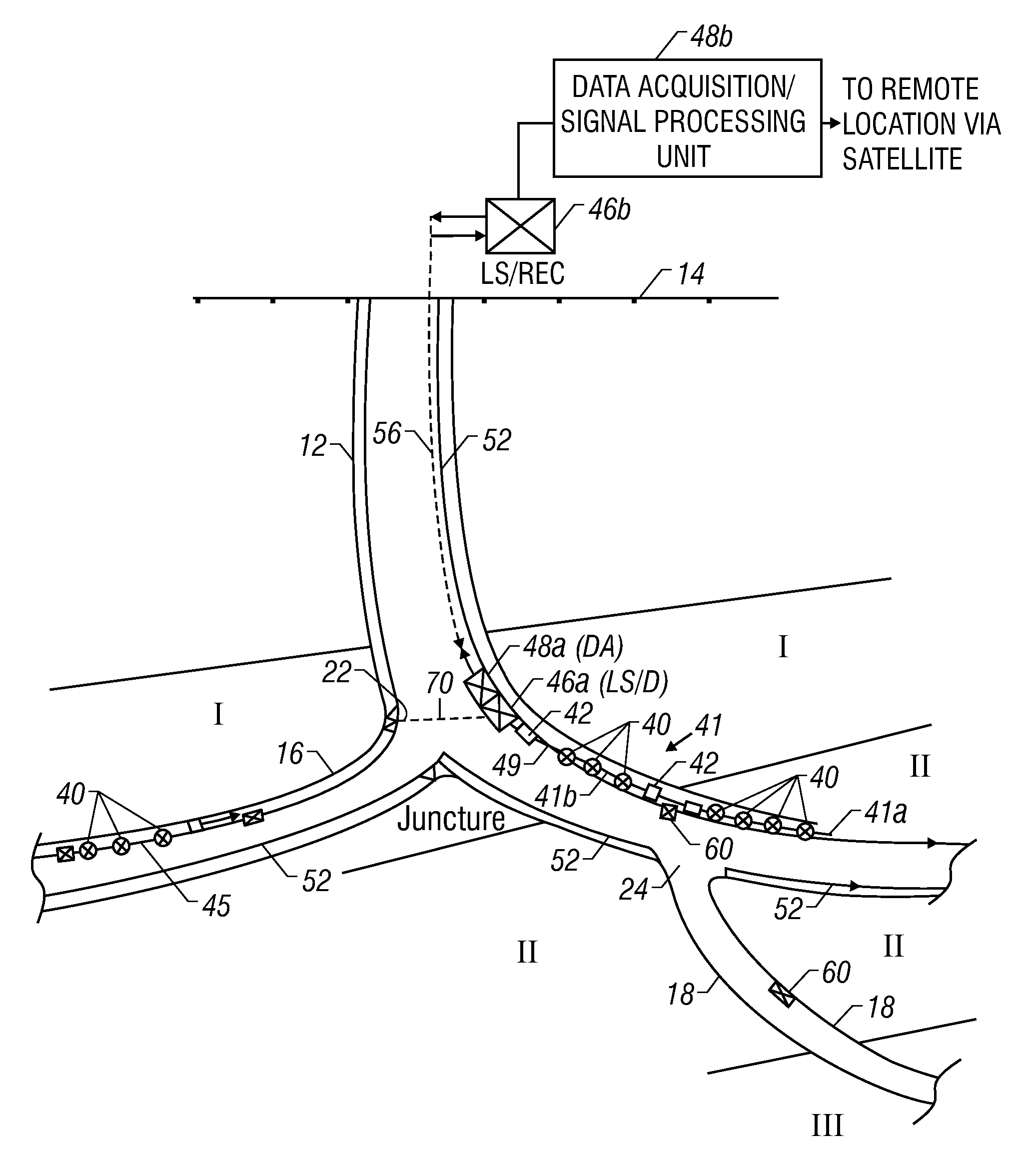
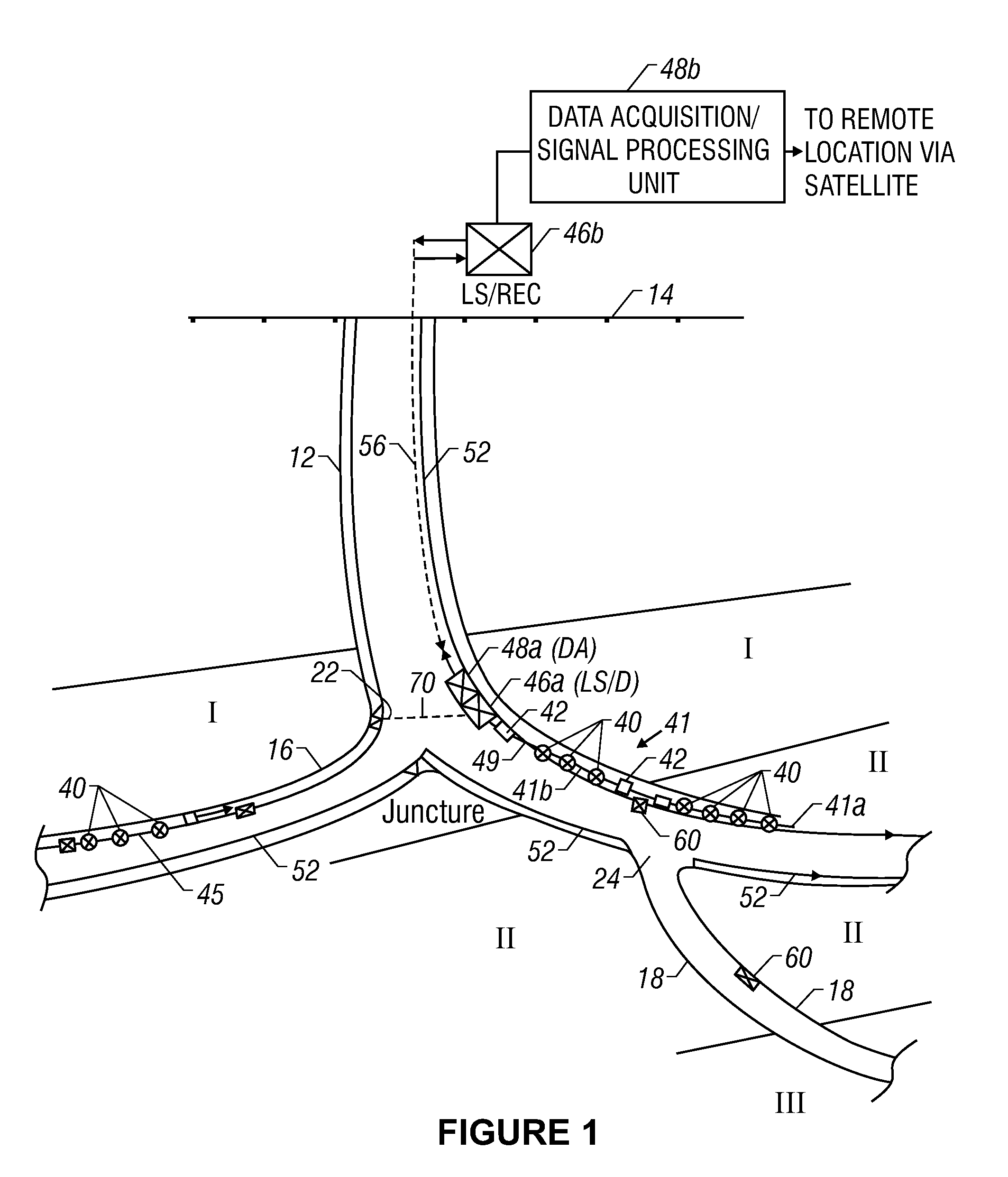
[0040]FIG. 1 shows an exemplary main or primary wellbore 12 formed from the surface 14 and lateral wellbores 16 and 18 formed from the main wellbore 18. For the purpose of explanation, and not as any limitation, the main wellbore 12 is partly formed in a producing formation or pay zone I and partly in a non-producing formation or dry formation II The lateral wellbore 16 extends from the main wellbore 12 at a juncture 24 into a second producing formation III. For the purposes of illustration, the wellbores herein are shown drilled from land, however, this invention is equally applicable to offshore wellbores. It should be noted that all wellbore configurations shown and described herein are to illustrate the concepts of present invention and shall not be construed to limit the inventions claimed herein.
[0041]In one application, a number of fiber optic sensors 40 are place in the wellbore 12. A single or a plurality of fiber optic sensors 40 may be used so as to install the desired nu...
PUM
Abstract
The present disclosure provides systems utilizing fiber optics for monitoring downhole parameters and the operation and conditions of downhole tools and controlling injection operations based on measurements in an injection well and/or a production well.
Description
CROSS-REFERENCE TO RELATED APPLICATIONS[0001]This application is a divisional application of U.S. patent application Ser. No. 10 / 447,855, filed on May 29, 2003 which is a divisional application of U.S. patent application Ser. Nos. 09 / 872,591 now U.S. Pat. Nos. 6,588,266 and 09 / 070,953 now U.S. Pat. No. 6,268,911. Divisional application Ser. No. 09 / 872,591 of U.S. patent application Ser. No. 09 / 070,953 has issued as U.S. Pat. No. 6,268,911. U.S. application Ser. No. 09 / 923,059, now abandoned, is a divisional of U.S. patent application Ser. Nos. 09 / 070,953 and 09 / 872,591. The present claims are based on a restriction requirement in the divisional application Ser. No. 09 / 872,591.[0002]U.S. patent application Ser. No. 09 / 070,953 claims priority from Provisional U.S. Patent Applications Ser. Nos. 60 / 045,354 filed on May 2, 1997; 60 / 048,989 filed on Jun. 9, 1997; 60 / 052,042 filed on Jul. 9, 1997; 60 / 062,953 filed on Oct. 10, 1997; 67 / 073425 filed on Feb. 2, 1998; and 60 / 079,446 filed on M...
Claims
Application Information
Patent Timeline
Application Date:The date an application was filed.
Publication Date:The date a patent or application was officially published.
First Publication Date:The earliest publication date of a patent with the same application number.
Issue Date:Publication date of the patent grant document.
PCT Entry Date:The Entry date of PCT National Phase.
Estimated Expiry Date:The statutory expiry date of a patent right according to the Patent Law, and it is the longest term of protection that the patent right can achieve without the termination of the patent right due to other reasons(Term extension factor has been taken into account ).
Invalid Date:Actual expiry date is based on effective date or publication date of legal transaction data of invalid patent.