Method of Making a Metal Bellows Assembly Having an Intermediate Plate

a technology of metal bellows and intermediate plates, which is applied in the direction of manufacturing tools, mechanical equipment, and sanders, etc., can solve the problems of insufficient variation of measured inductance to provide accurate measurements, and inaccessibility for long periods of time, and achieve the effect of convenient movemen

Inactive Publication Date: 2009-07-30
MEDOS INT SARL
View PDF40 Cites 21 Cited by
  • Summary
  • Abstract
  • Description
  • Claims
  • Application Information

AI Technical Summary

Benefits of technology

[0018]The formation of a bellows made up of a stack of a predetermined number of ring-convolutions and having an intermediate plate supported within said stack, according to the present invention is achieved by starting with a supply of thin metal rings, each ring having a first outer diameter defining a first outer edge and a first inner diameter, defining a first inner edge. A pair of these metal rings are positioned one on top of the other in a contiguous relation to each other and their adjacent inside edges are welded together to form a ring-convolution. This process is repeated until a sufficient number of ring-convolutions are made to eventually make the desired bellows. Before these separate ring-convolutions are fused to each other, an intermediate plate and a support ring are made. The intermediate plate is a disc of metal that is sized smaller than the inside diameter of the rings and is secured to the support ring. The support ring is then positioned between two formed ring-convolutions in contiguous relationship and the three abutting outside edges are welded to each other to form a support plate convolution. The already made ring-convolutions and the support plate convolution are then stacked in the desired order and in contiguous relationship.
[0019]All not-yet welded adjacent outside edges of said ring-convolutions and said support plate convolution are then welded to form the bellows. A bottom plate is formed and welded to the outside edge of the bottommost ring-convolution and a top ring is finally welded to the uppermost convolution to complete the bellows. The top ring is meant to be welded to a base plate of an infusion pump. The method includes steps for holding the rings to be welded into a jig and thereafter moving the jig with respect to the welder, or moving the welder with respect to the jig. The welder preferably includes the use of a laser wherein the output beam of the laser may be easily moved along the held rings by appropriate optics, but the welder may also be an arc-TIG type.

Problems solved by technology

Since these pumps are surgically implanted within a patient, they are for the most part, inaccessible for long periods of time.
At fluid levels greater than about 20 ml and because of the increasing distance between the coil and the bottom plate at those greater volumes, the measured inductance doesn't vary sufficiently to provide accurate measurements.

Method used


Image

  • Method of Making a Metal Bellows Assembly Having an Intermediate Plate
  • Method of Making a Metal Bellows Assembly Having an Intermediate Plate
  • Method of Making a Metal Bellows Assembly Having an Intermediate Plate

Examples


Embodiment Construction

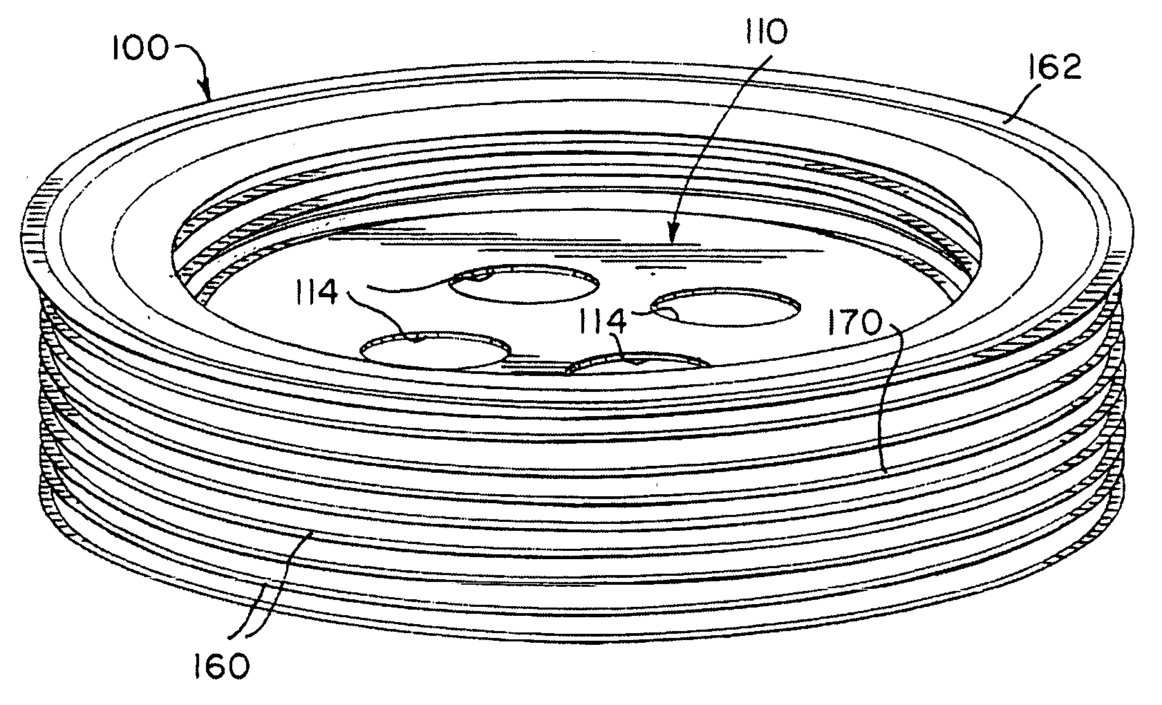
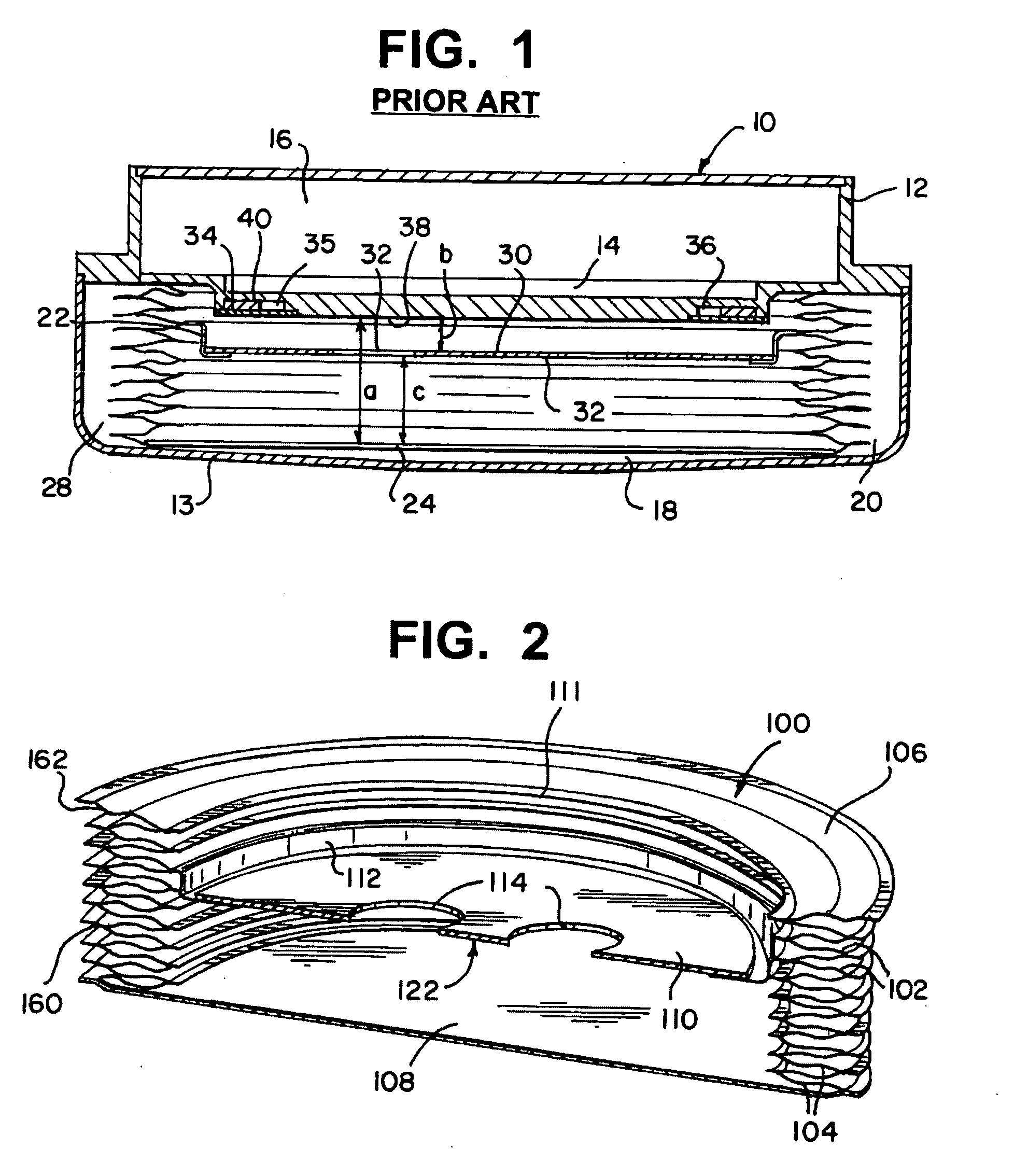
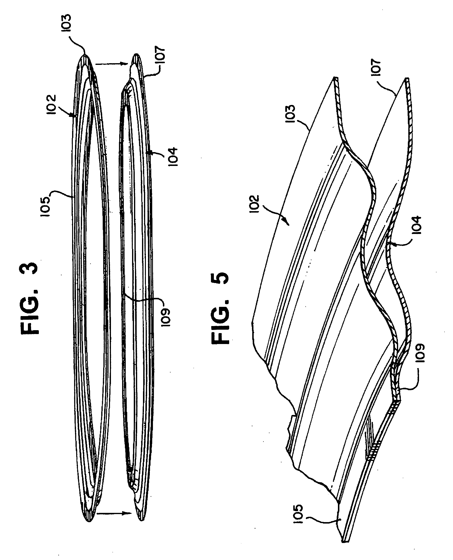
[0035]Referring to FIGS. 2 and 12, a bellows 100 (cross-sectional view in FIG. 2) is shown including a plurality of upper diaphragm rings 102 (hereinafter called “upper rings”) edge-welded to a plurality of lower diaphragm rings 104 (hereinafter called “lower rings”, a top ring 106, a bottom plate108, an intermediate plate 110 and an intermediate-plate support ring 112. The bellows 100 shown in FIG. 12 is manufactured primarily by welded pre-cut and formed parts together in a predetermined order, as described below.

[0036]According to the method of manufacture of the present invention, each upper and lower ring 102, 104, top ring 106, bottom plate 108, an intermediate plate 110 and an intermediate-plate support ring 112 is made by cutting a predetermined shape from an appropriate bio-compatible material, such as titanium, stainless steel, an appropriate composite, alloy, or a laminate made up of different metals and / or composites.

[0037]All the main parts of the bellows 100, including...


PUM

PropertyMeasurementUnit
volumesaaaaaaaaaa
volumeaaaaaaaaaa
volumeaaaaaaaaaa

Abstract

The formation of a bellows made up of a stack of a predetermined number of ring-convolutions and having an intermediate plate supported within said stack is achieved by supplying several thin metal rings, each having inner and outer edges. A pair of these metal rings are positioned in contiguous relationship and their adjacent inside edges are welded together to form a ring-convolution. This process is repeated until a sufficient number of ring-convolutions are made to eventually make the desired bellows. Before these separate ring-convolutions are fused to each other, an intermediate plate and a support ring are made. The intermediate plate is a disc of metal that is sized smaller than the inside diameter of the rings and is secured to the support ring. The support ring is then positioned between two formed ring-convolutions in contiguous relationship and the three abutting outside edges are welded to each other to form a support plate convolution. The already made ring-convolutions and the support plate convolution are then stacked in the desired order and in contiguous relationship. All not-yet welded adjacent outside edges of said ring-convolutions and said support plate convolution are then welded to form the bellows. A bottom plate is formed and welded to the outside edge of the bottommost ring-convolution and a top ring is finally welded to the uppermost convolution to complete the bellows. The top ring is meant to be welded to a base plate of an infusion pump.

Description

RELATED APPLICATIONS[0001]This application is a continuation-in-part of U.S. Provisional patent application Ser. No. 09 / 742,622 filed on Oct. 31, 2005, entitled “Implantable Pump with Reservoir with Level Detector” (Docket No. COD5075USPSP), and U.S. Non-Provisional patent application Ser. No. 11 / 552,343 filed on Oct. 24, 2006, entitled “Implantable Pump with Reservoir Level Detector” (Docket No. COD5075USNP), the disclosures of which are hereby incorporated by reference in their entirety.BACKGROUND OF THE INVENTION[0002]1) Field of the Invention[0003]The present invention generally relates to the method of manufacture of metal bellows of the type used to form a fluid reservoir in implantable infusion pumps, and more particularly, to the method of manufacture of such metal bellows having an intermediate plate to aid in accurate sensing of the volume of the bellows.[0004]2) Discussion of Related Art[0005]Extremely thin-gauge titanium welded bellows are commonly used in implantable in...

Claims


Application Information

Patent Timeline
Patent Type & Authority Applications(United States)
IPC IPC(8): B23K9/24
CPCA61M5/14276A61M5/1486B23K9/028Y10T29/49877B23K26/28F16J3/047B23K26/206
Inventor MARGAIRAZ, PHILIPPEPRINGALLE, PIERREPETITHORY, JEAN-SEBASTIEN
Owner MEDOS INT SARL
Why Eureka
Try Eureka