

Fluorescence-activated cell detector
a fluorescence-activated cell and detector technology, applied in the direction of radiation measurement, optical radiation measurement, spectral modifiers, etc., can solve the problems of inconvenient use, inconvenient use, and inconvenient use, and achieve the effect of better use of the gain
- Summary
- Abstract
- Description
- Claims
- Application Information
AI Technical Summary
Benefits of technology
Problems solved by technology
Method used
Image

Examples
embodiment 100
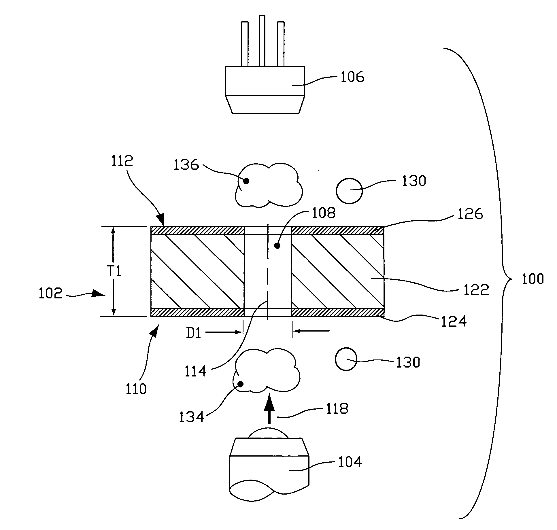
[0038]A schematic illustrating a generalized operable arrangement of structure employed in embodiments structured according to certain principles of the invention is indicated generally at 100 in FIG. 1. As illustrated, embodiment 100 includes an opaque member, generally indicated at 102, disposed between a radiation source 104 and a radiation detector 106. At least one orifice 108 is disposed in opaque member 102 to provide a flow path between a first side, generally indicated at 110, and a second side, generally indicated at 112. Orifice 108 may be characterized as having a through-axis 114 extending between the first and second sides 110 and 112 of opaque member 102, respectively.
[0039]Both of the thickness, T1, of an opaque member and characteristic size, D1, of an orifice 108 are typically sized in agreement with a size of a particle of interest to promote single-file travel of the particle through the opaque member, and to have only one particle inside the orifice at a time. I...
embodiment 140
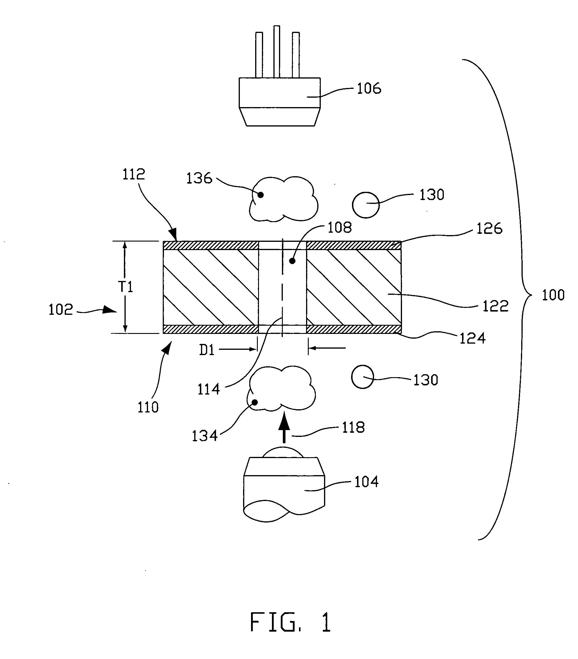
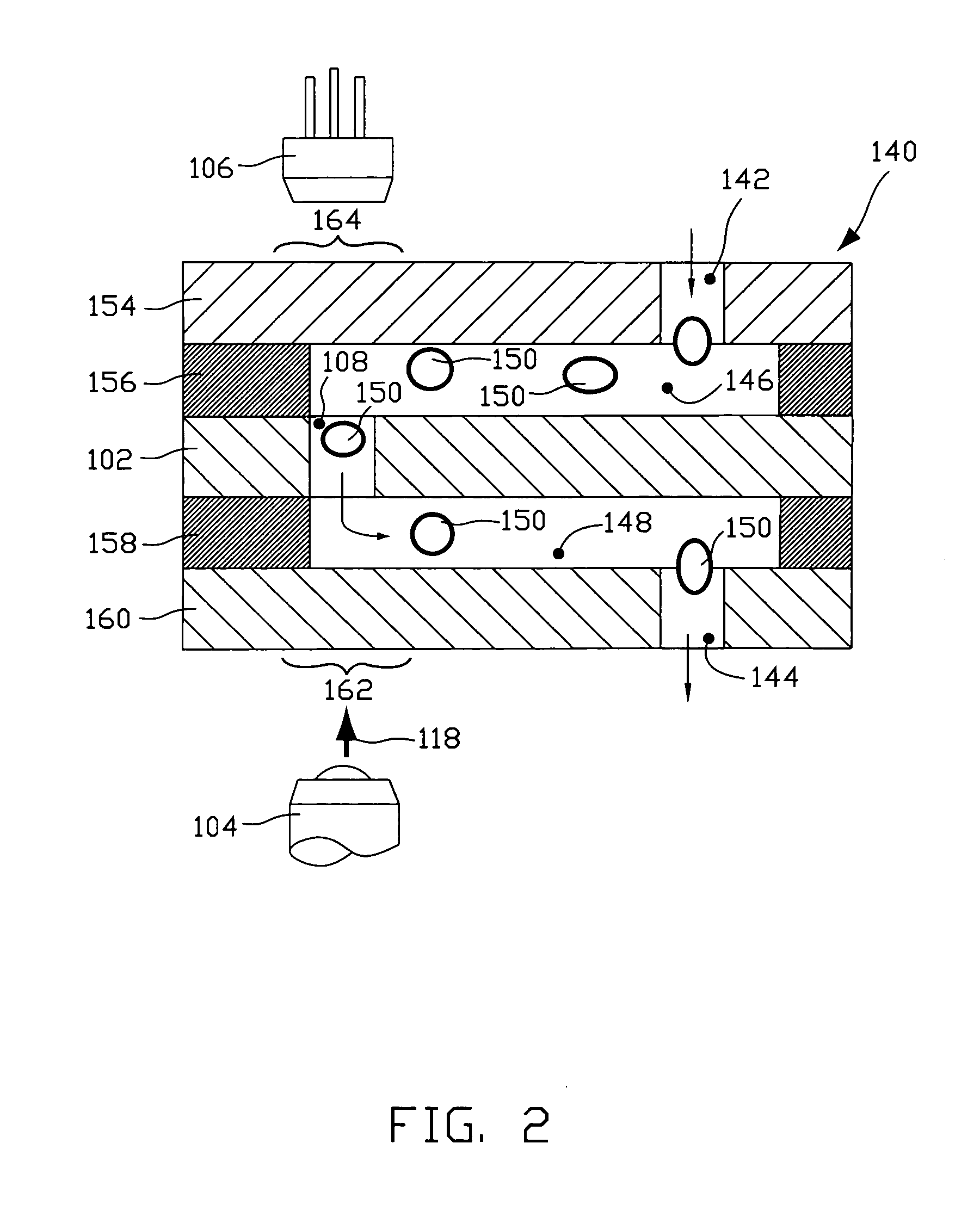
[0048]Although both of supply chamber 142 and waste chamber 144 are illustrated as being open, it is within contemplation for one or both to be arranged to substantially contain the fluid sample within a plumbing device that includes a multilayer embodiment 140. Also of note, although a top-down fluid flow is illustrated in FIG. 2, fluid flow may be established in either direction through orifice 108. In one reverse-flow configuration, the positions of supply chamber 142 and waste chamber 144 would simply be reversed from their illustrated positions. In an alternative reverse-flow arrangement, the positions of the radiation source 104 and detector 106 would be reversed from their illustrated positions.
[0049]The multilayer plumbing arrangement 140 illustrated in FIGS. 2 and 3 includes a top cap layer 154, a top channel layer 156, an opaque member 102, a bottom channel layer 158, and a bottom cap layer 160. Such layers can be stamped, e.g. die cut, or manufactured by using a laser or ...
embodiment 220
[0059]With reference now to FIG. 11, a schematic illustrating a generalized operable arrangement employed in a currently more preferred embodiment structured according to certain principles of the invention is indicated generally at 220. As illustrated, embodiment 220 includes a barrier layer, generally indicated at 222, disposed between a radiation waveguide 226 and a radiation detector 106. In the currently most preferred embodiments, barrier layer 222 is at least substantially opaque to resist propagation of radiation there-through, in a thickness direction. An operable barrier layer 222 may be structured similar to opaque member 102, described above, and may therefore include one or more optional coating 124, 126. Alternatively, a bare core 122 may directly resist propagation of radiation there-through.
[0060]Waveguide 226 permits applied excitation radiation 118 to impinge on an interrogation zone, such as zone 134. An operable waveguide 226 may include a simple window, a fiber ...
PUM
| Property | Measurement | Unit |
|---|---|---|
| thickness | aaaaa | aaaaa |
| thickness | aaaaa | aaaaa |
| acute angle | aaaaa | aaaaa |
Abstract
Description
Claims
Application Information