Paper output mechanism

Inactive Publication Date: 2009-07-30
NORITZ CORP
View PDF10 Cites 18 Cited by
  • Summary
  • Abstract
  • Description
  • Claims
  • Application Information

AI Technical Summary

Benefits of technology

[0016]This provides an optimum paper output mechanism for a pri

Problems solved by technology

If the paper placement point varies in this manner, this increases the likelihood that, particularly when pieces of paper are conveyed by a belt conveyer

Method used


Image

  • Paper output mechanism
  • Paper output mechanism
  • Paper output mechanism

Examples


first example embodiment

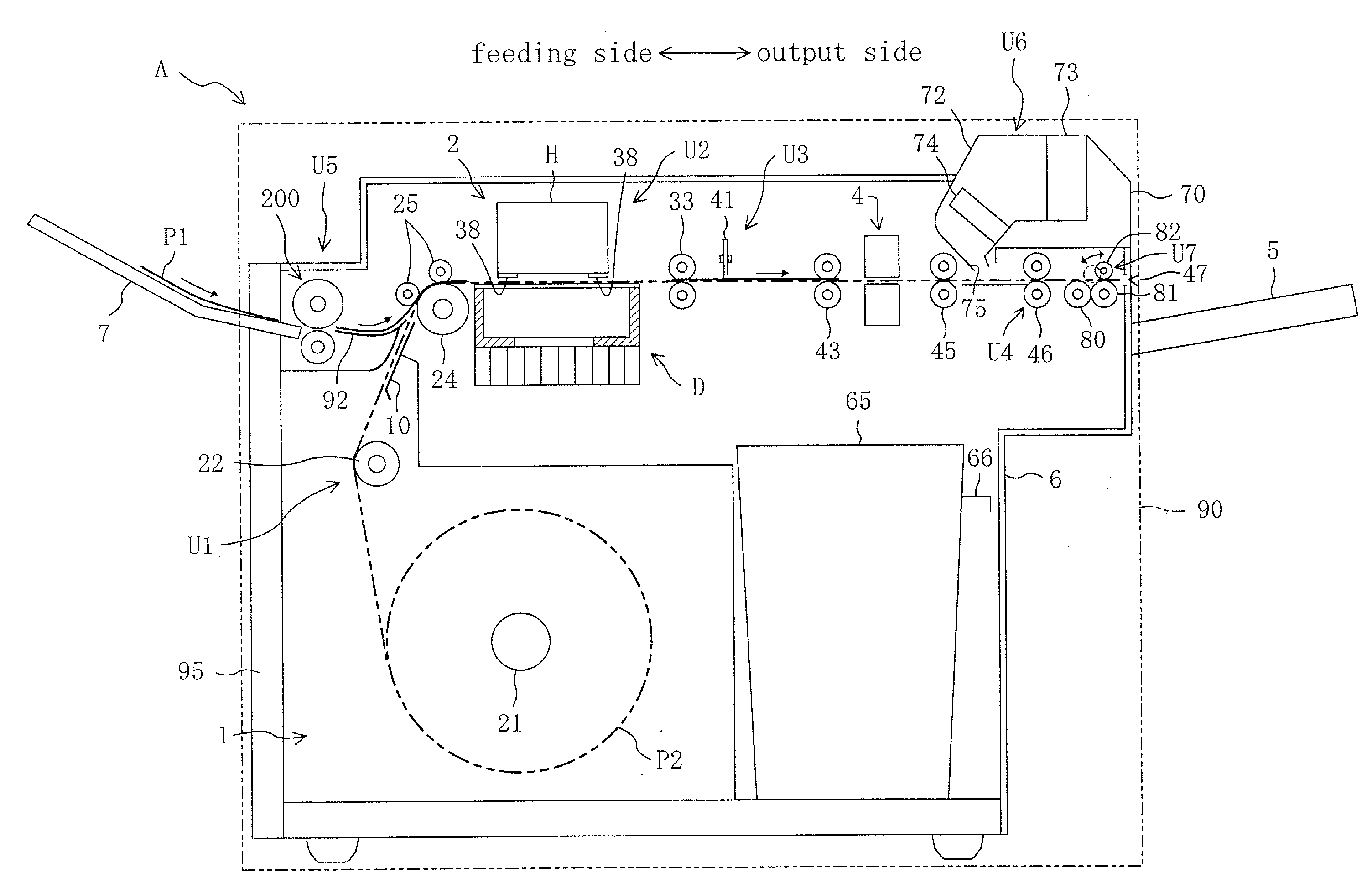
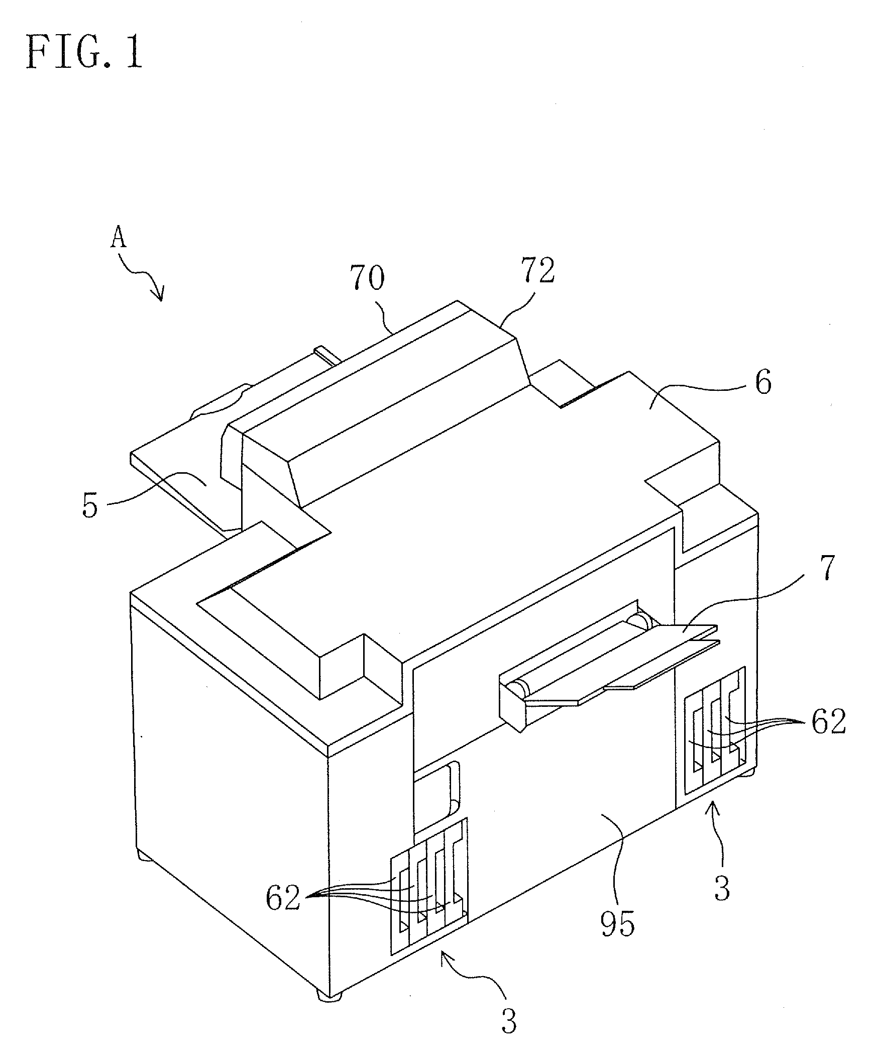
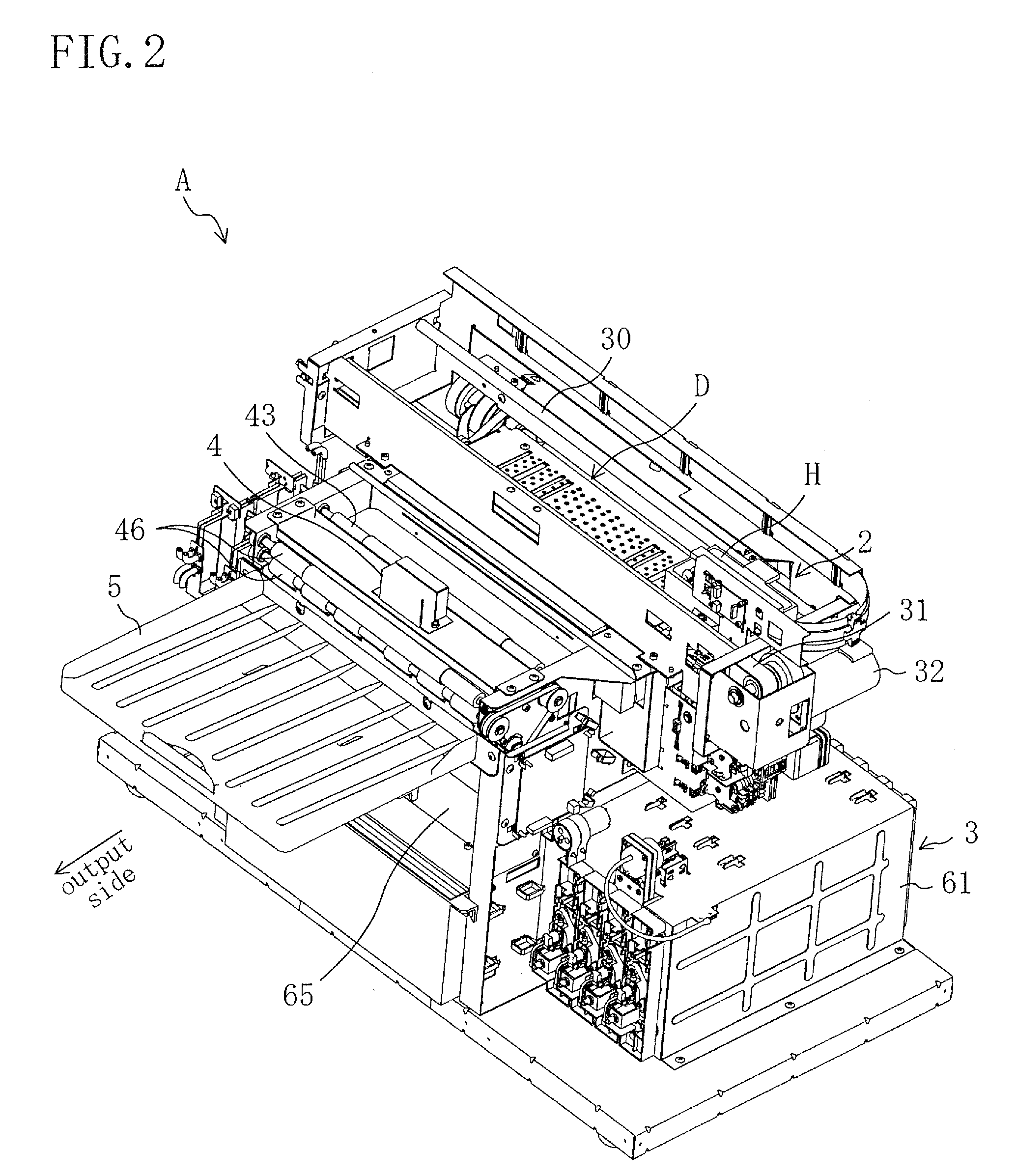
[0031]FIG. 1 shows the appearance of an inkjet printer A including a decurling unit as a paper output mechanism according to a first example embodiment, and FIGS. 2 to 5 show the internal structure of the inkjet printer A. The inkjet printer A is used for a photographic printing system and, for example, used for printing photographic images on printing paper P1 or P2 based on image data transmitted via a communication cable from a reception block for obtaining the image data and correcting it as necessary. More specifically, the inkjet printer A is configured to be capable of performing an automatic printing for pulling out one end of a long roll of printing paper P2 and printing an image on the printing surface of the roll of printing paper P2 (hereinafter, referred to as a paper web P2) and a manual-feed printing for printing an image on the printing surface of a sheet of printing paper P1 (hereinafter, referred to as a paper sheet P1) previously cut in a given size.

[0032]When in ...

second example embodiment

[0091]FIG. 12 is a perspective view showing the structure of an inkjet printer according to a second example embodiment. This example embodiment is different from the first example embodiment in that a conveyance unit 100 and an collection unit 110 are provided instead of the paper output tray 5. Therefore, the same parts are identified by the same reference numerals as in the first example embodiment and a description is given only of different points.

[0092]As shown in FIGS. 12 and 13, the inkjet printer A includes a printer body 90, a conveyance unit 100 disposed downstream of the printer body 90, and a collection unit 110 disposed downstream of the conveyance unit 100 in the direction of paper conveyance. The printer body 90 has substantially the same structure as described in the first example embodiment and, therefore, a description thereof is not given.

[0093]The conveyance unit 100 constitutes a paper placement part for receiving pieces of printing paper P1 or P2 output throug...


PUM

PropertyMeasurementUnit
Speedaaaaaaaaaa

Abstract

A paper output mechanism includes: a roller pair composed of a first roller and a second roller travelable around the first roller and configured, when the second roller is in a first position, to output a piece of paper to a paper placement part by pinching the piece of paper between the first and second rollers and driving at least one of the first and second rollers into rotation with an actuator; and a roller position changing mechanism for switching the second roller between the first position and a second position located closer to the paper output side than the first position. When the trailing edge of the piece of paper is sent out to the paper placement part, the roller position changing mechanism changes the second roller from the first position to the second position.

Description

CROSS-REFERENCE TO RELATED APPLICATION[0001]This application claims priority under 35 USC 119 to Japanese Patent Application No. 2008-018213 filed on Jan. 29, 2008, the entire contents of which are incorporated herein by reference.BACKGROUND[0002]The techniques disclosed in this specification relate to paper output mechanisms for outputting a piece of paper conveyed to the terminal end of a paper conveyance path from the terminal end thereof to a paper placement part disposed below the terminal end.[0003]It is so far well known that in printers such as for photo printing systems their printer body is internally provided with a paper conveyance path along which paper is conveyed. The terminal end of the paper conveyance path is located in the vicinity of a paper output port in the printer body. A piece of paper (printed piece of paper) conveyed to the terminal end of the paper conveyance path is output from the terminal end through the paper output port by a paper output mechanism, s...

Claims


Application Information

Patent Timeline
IPC IPC(8): B65H29/20
CPCB65H29/12G03G15/6576G03G15/6552B65H2301/512565
Inventor YAMAMOTO, AKIHITO
Owner NORITZ CORP
Why Eureka
Try Eureka