Droplet emitting apparatus having piezoelectric voltage generator and method of emitting a droplet using the same

a piezoelectric voltage generator and droplet technology, applied in the field of droplet emitting apparatus, can solve the problem that the inconvenient solution of the inkjet technique is not suitable for the inkjet technology, and achieve the effect of reducing the distan

Active Publication Date: 2009-07-30
SAMSUNG ELECTRONICS CO LTD
View PDF5 Cites 8 Cited by
  • Summary
  • Abstract
  • Description
  • Claims
  • Application Information

AI Technical Summary

Benefits of technology

[0020]According to another aspect of the present invention, there is provided a method of emitting a droplet. The method includes: reducing a distance between a target object onto which a solution contained in a solution tank is emitted and a nozzle through which to the solution is emitted until the distance is greater than 0 and equal to or less than a critical distance that is the maximum distance at which a liquid bridge is formed between the target object and a front end of the nozzle; preparing a voltage generator including a ...

Problems solved by technology

However, since the inkjet technique involves applying heat to a solution (or ink), the ...

Method used


Image

  • Droplet emitting apparatus having piezoelectric voltage generator and method of emitting a droplet using the same
  • Droplet emitting apparatus having piezoelectric voltage generator and method of emitting a droplet using the same
  • Droplet emitting apparatus having piezoelectric voltage generator and method of emitting a droplet using the same

Examples


Embodiment Construction

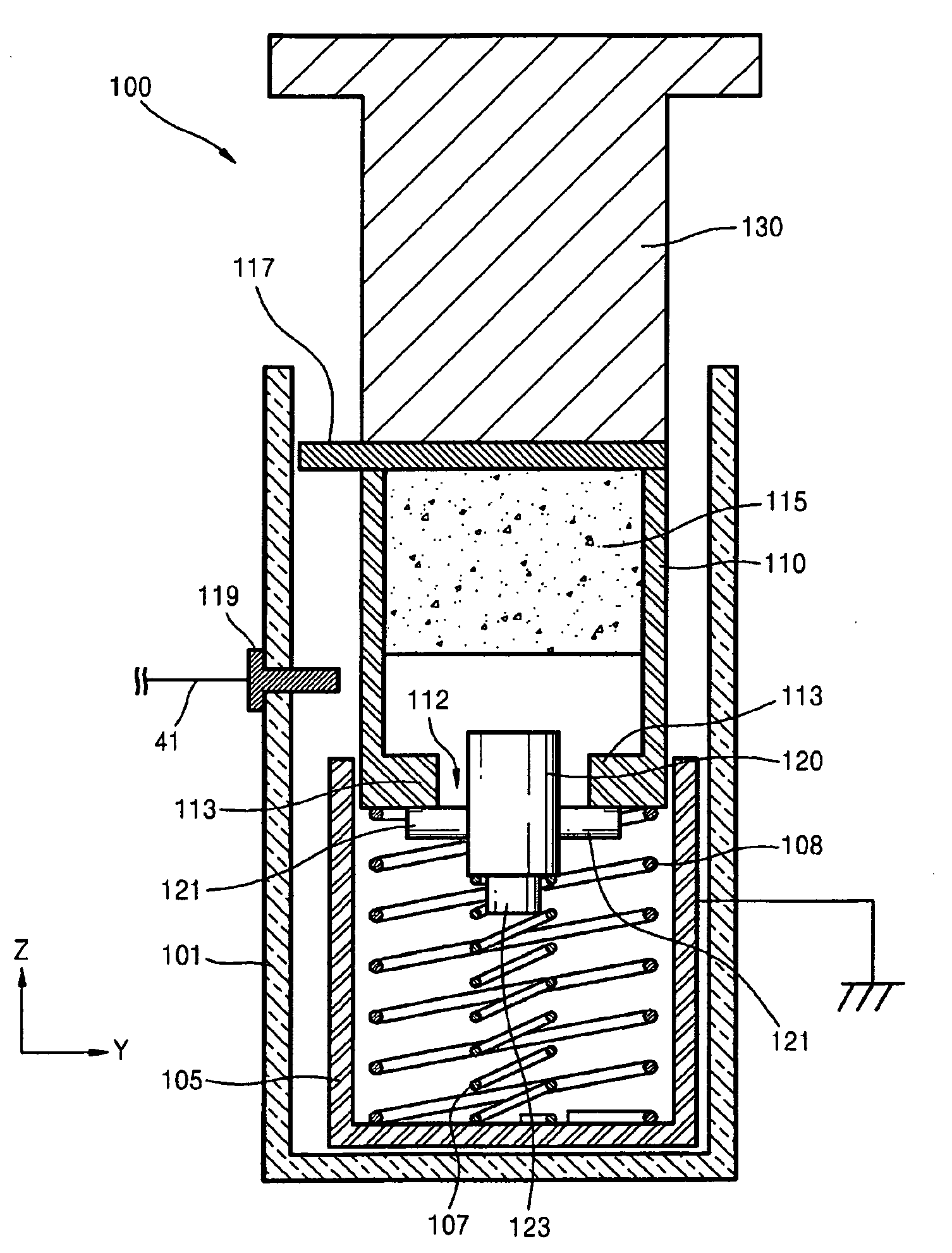
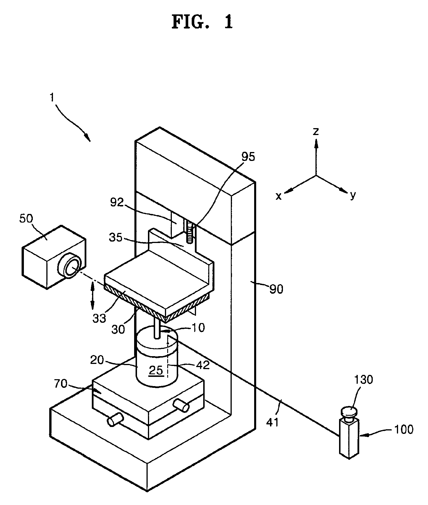
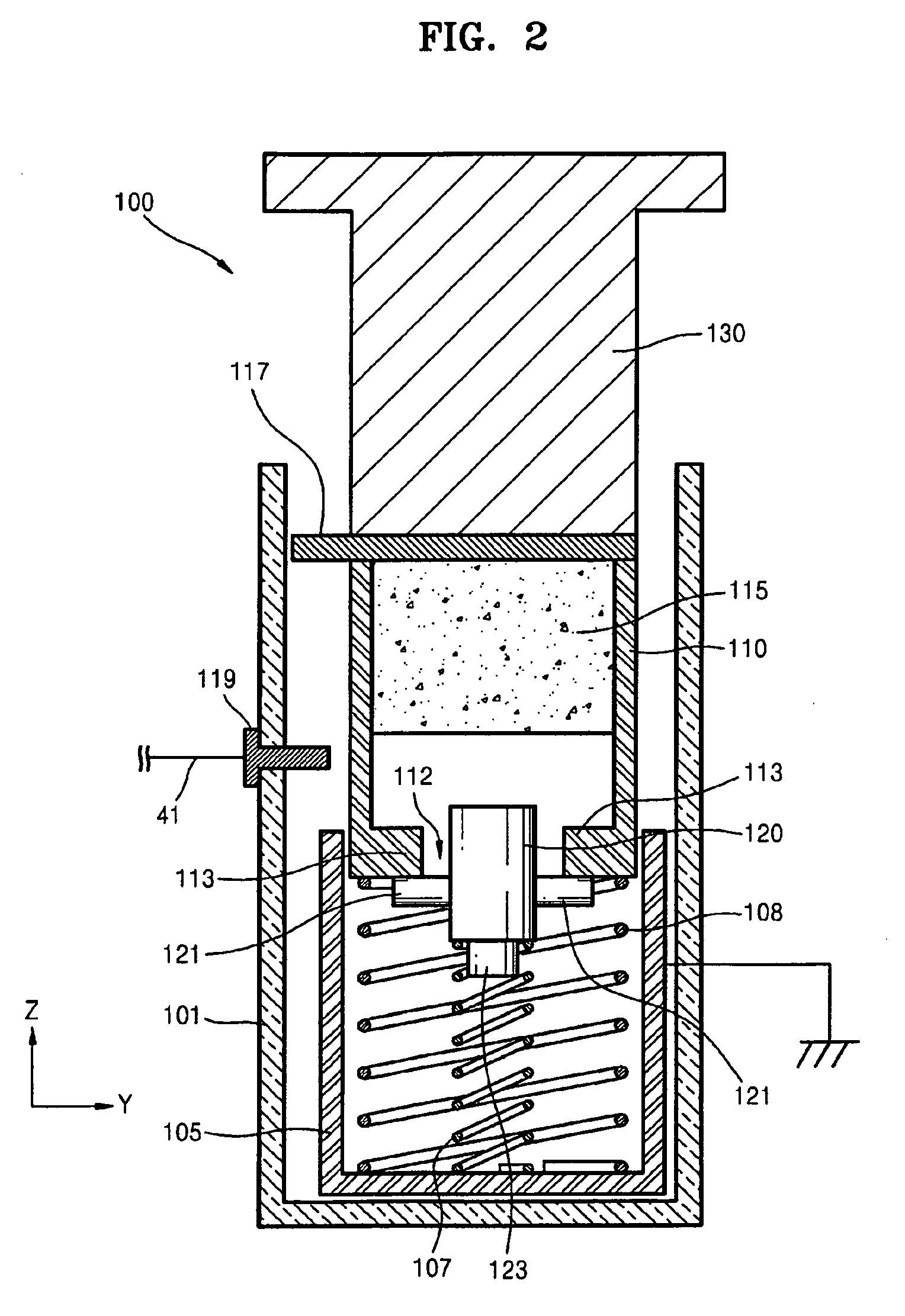
[0030]FIG. 1 is a perspective view of a droplet emitting apparatus 1 according to an embodiment of the present invention. FIG. 2 is a cross-sectional view of a voltage generator 100 of the droplet emitting apparatus 1 illustrated in FIG. 1, according to an embodiment of the present invention.

[0031]Referring to FIG. 1, the droplet emitting apparatus 1 according to the current embodiment includes a solution tank 20 for containing a solution 25, a nozzle 10 including an opening (refer to 11 in FIG. 3A) through which one or more very small droplets of the solution 25 are emitted, and a voltage generator 100 for applying a voltage to the solution 25. The nozzle 10, which has the shape of a capillary tube, includes a rear end (refer to 12 in FIG. 3A) and a front end (refer to 13 in FIG. 3A). The rear end of the nozzle is immersed in the solution 25 contained in the solution tank 20, while the front end of the nozzle protrudes from the solution tank 20. The opening 11 is formed through the...


PUM


Abstract

Provided are a droplet emitting apparatus and a method of emitting droplets using the same. The apparatus includes a solution tank for containing a solution; a nozzle including an opening through which at least a droplet of the solution is emitted; and a voltage generator including a piezoelectric material for generating a voltage by instantaneous pressure application, wherein the voltage generated by the pressure to the piezoelectric material is applied to the solution in order for the at least a droplet of the solution to be emitted through the nozzle

Description

CROSS-REFERENCE TO RELATED PATENT APPLICATION[0001]This application claims the benefit of Korean Patent Application No. 10-2008-0008033, filed on Jan. 25, 2008, in the Korean Intellectual Property Office, the disclosure of which is incorporated herein in its entirety by reference.BACKGROUND OF THE INVENTION[0002]1. Field of the Invention[0003]The present invention relates to a droplet emitting apparatus, and more particularly, to a droplet emitting apparatus for emitting at least a droplet onto a target object by using an electric charge concentration and a liquid bridge breakup, and a method of emitting a droplet using the apparatus.[0004]2. Description of the Related Art[0005]In general, a droplet emitting apparatus emits one or more very small droplets of a solution onto a target object such as a substrate or paper. There are a variety of techniques of emitting droplets, including an inkjet technique applied to an inkjet printer. However, since the inkjet technique involves apply...

Claims


Application Information

Patent Timeline
IPC IPC(8): B41J25/308B41J29/38
CPCB01L3/0268B01L2400/0415Y10T436/2575B41J2/175B41J2/04B41J2/045B41J2/06B01L3/0262B41J29/393
Inventor LEE, BEOM-SEOKMOON, DUSTINLEE, JEONG-GUNCHO, HYE-JUNGKANG, IN-SEOKHONG, JIN-SEOK
Owner SAMSUNG ELECTRONICS CO LTD
Why Eureka
Try Eureka