Straight through cement mixer

Active Publication Date: 2009-07-30
SERVA GROUP
View PDF9 Cites 4 Cited by
  • Summary
  • Abstract
  • Description
  • Claims
  • Application Information

AI Technical Summary

Benefits of technology

[0026]The water jet orifices are angled in orientation so that their discharge is directed inwardly towards the mixing chamber. All of the existing technology with annular adjustable orifices is aligned in an axial direction. These axial designs require the flow direction to be “turned” or deflected beyond the jet to hit the desired mixing chamber location. The turning of high velocity flow causes high wear on mixer parts.
[0027]Also, the water jets are located axially downstream of the recirculation jets.

Problems solved by technology

First, the earlier mixer was not of a straight through type.
Because of this design, it was more difficult to flush out and clean the inside of the mixer.
Also, it was not possible to see straight through the mixer by breaking open the piping connection at the inlet 52, thus making it more difficult to see inside the mixer to troubleshoot or determine if it was clean when doing maintenance.
Also, the four annular water jets of the earlier mixer had less flow capacity, resulting in higher velocity of liquid streams within the mix chamber to obtain comparable

Method used


Image

  • Straight through cement mixer
  • Straight through cement mixer
  • Straight through cement mixer

Examples


Example

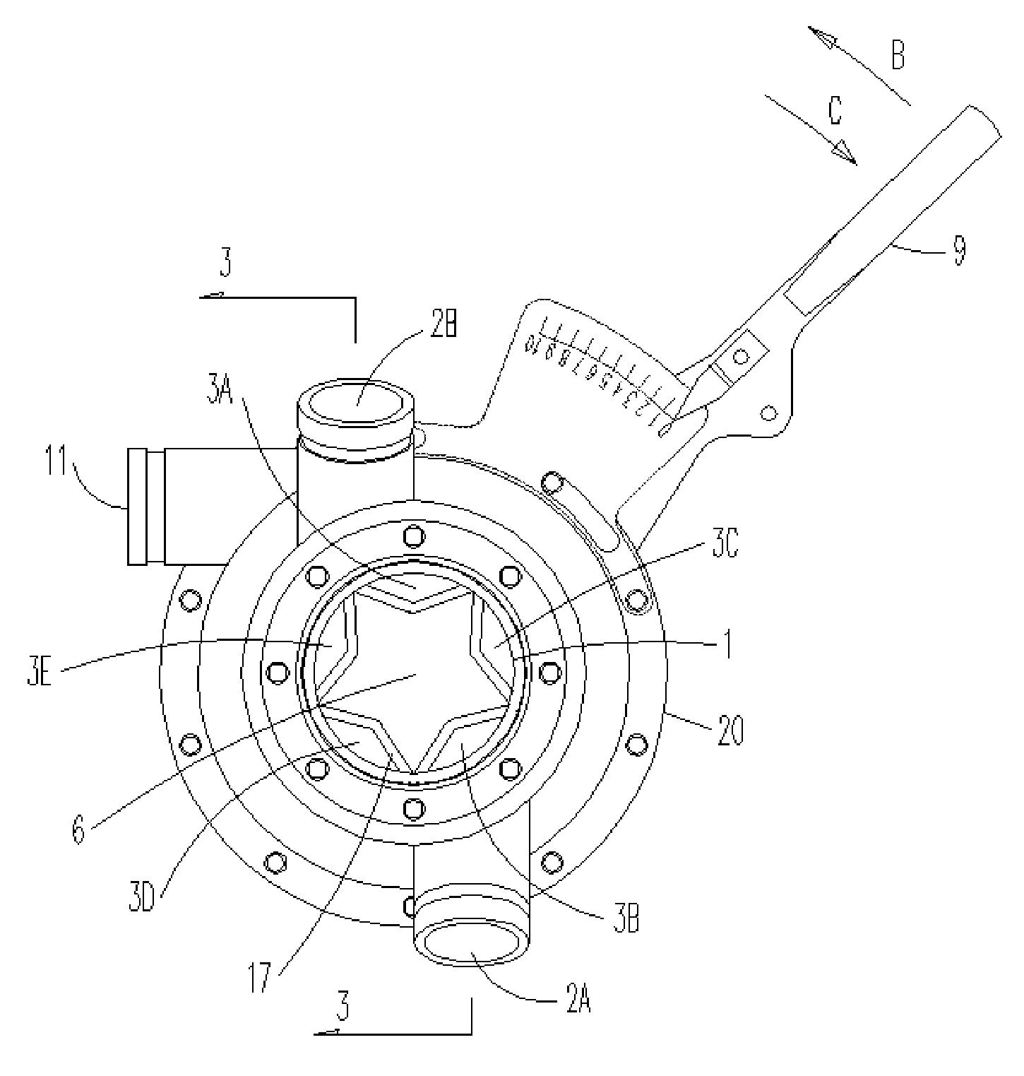
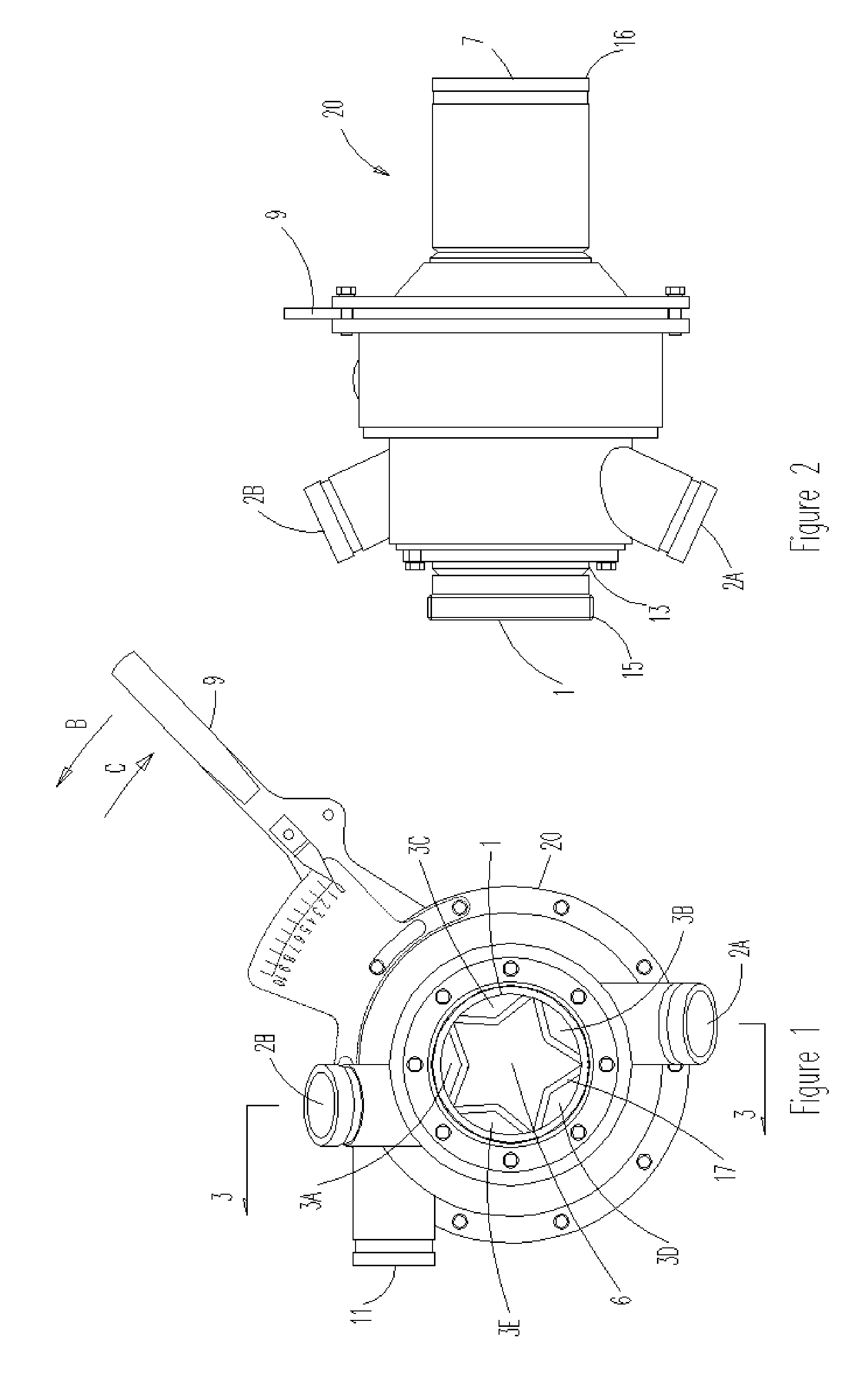
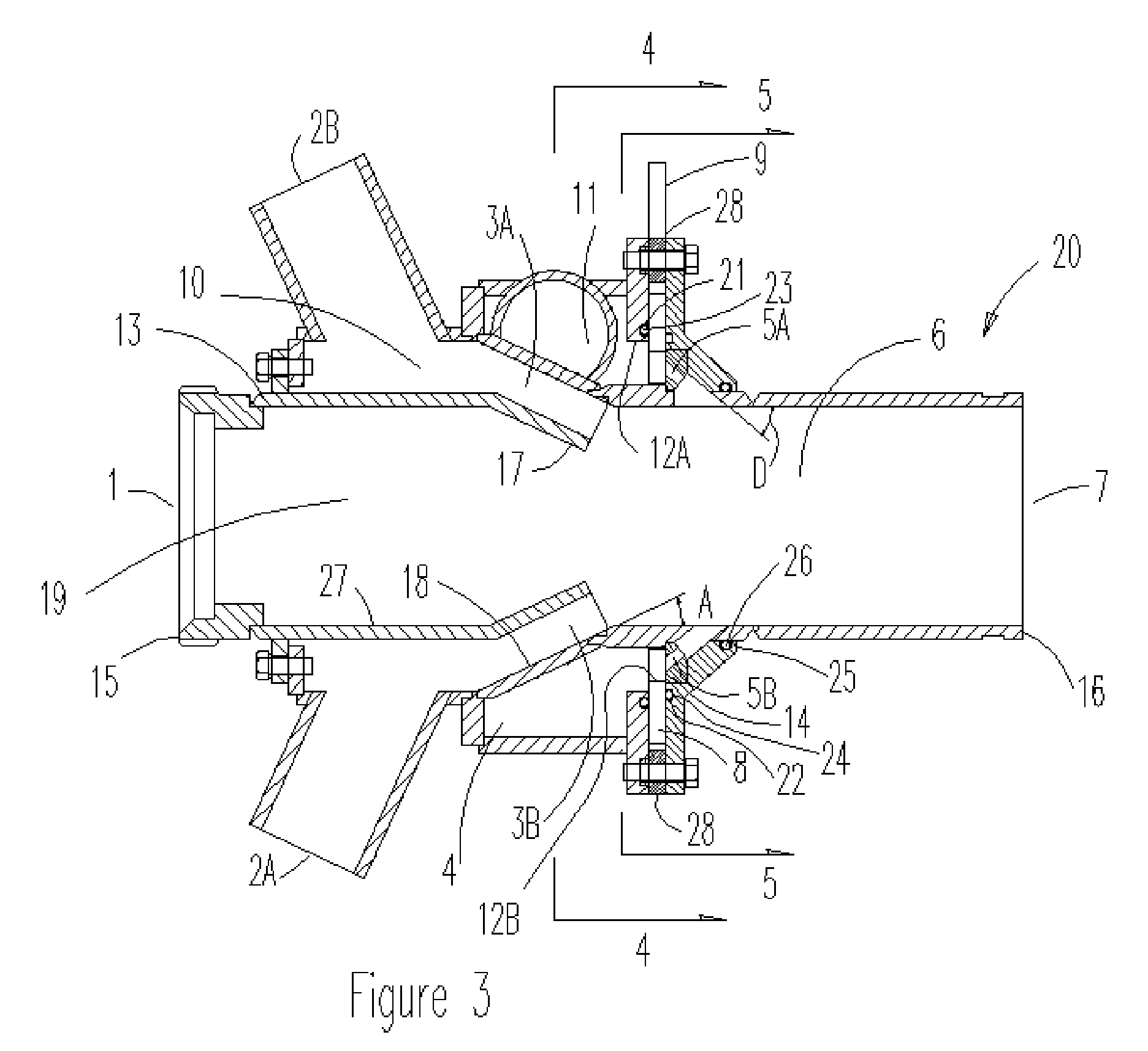
[0037]Referring now to the drawings and initially to FIGS. 2 and 3, the present invention is a cement mixing method and the mixer 20 used in that method for mixing cement that will be used in cementing oil wells. The overall typical system and equipment within which the mixer 20 is likely to be used are taught in U.S. Pat. No. 6,749,330. That teaching is incorporated herein by reference.

[0038]As explained in detail in U.S. Pat. No. 6,749,330, typically a cement mixer discharges from its outlet end into a diffuser and subsequently into a mixing tank. A recirculation pump is attached to the mixing tank and recirculates the contents of the mixing tank to recirculation flow inlets provided on the mixer. And, typically a mix water pump is connected to a supply of mix water and pumps that mix water to a mix water inlet provided on the mixer. Also, bulk cement is pneumatically delivered to the dry bulk cement inlet of the mixer. It is the cement mixer 20 that is the subject of the present ...


PUM

PropertyMeasurementUnit
Flow rateaaaaaaaaaa

Abstract

A cement mixing method for mixing cement used in cementing oil wells casing and the mixer used in that method. The mixer employs a straight bulk cement inlet, five annular recirculation jets and five annular water jet orifices located downstream of the recirculation jets so that all of the jets discharge at an angle towards the mixing chamber and the discharge from the water jet orifices intersects with the flow from the recirculation jets. This five jet, intersecting flow design allows for more thorough wetting of the cement powder with a smaller, lighter, less expensive and more durable mixer that is less inclined to foul and easier to clean.

Description

CROSS-REFERENCE TO RELATED APPLICATIONS[0001]The present application is a continuation in part application of U.S. patent application Ser. No. 12 / 021,415 for Straight Through Cement Mixer which was filed on Jan. 29, 2008. Applicant is the sole inventor of U.S. Pat. No. 6,749,330 that issued on Jun. 15, 2004 for Cement Mixing System for Oil Well Cementing. Applicant also is sole inventor of U.S. Pat. No. 5,571,281 that issue on Nov. 5, 1996 for Automatic Cement Mixing and Density Simulator and Control System and Equipment for Oil Well Cementing; is one of the co-inventors of U.S. Pat. No. 5,355,951 that issued on Oct. 18, 1994 for Method of Evaluating Oil or Gas Well Fluid Process; and is one of the co-inventors of U.S. Pat. No. 5,046,855 that issued on Sep. 10, 1991 for Mixing Apparatus.BACKGROUND OF THE INVENTION[0002]1. Field of the Invention[0003]The present invention is a high efficiency, high energy slurry mixer used primarily to mix oil field cement in a recirculating system f...

Claims


Application Information

Patent Timeline
IPC IPC(8): B01F15/02
CPCB01F3/1228B01F5/0475B28C7/126B01F5/106B28C5/06B01F5/048B01F23/54B01F25/3142B01F25/31423B01F25/53
Inventor ALLEN, THOMAS E.
Owner SERVA GROUP
Why Eureka
Try Eureka