
Phase locked loop calibration

a phase locked loop and calibration technology, applied in angle modulation, phase difference detection, electrical apparatus, etc., can solve the problems of high frequency of modulation signal amplification, oscillator gain variation, and high frequency of modulation signal, so as to facilitate noise reduction of error signal and facilitate smooth scaling control signal

Active Publication Date: 2009-07-30
TELEFON AB LM ERICSSON (PUBL)
View PDF5 Cites 2 Cited by
  • Summary
  • Abstract
  • Description
  • Claims
  • Application Information

AI Technical Summary

Benefits of technology

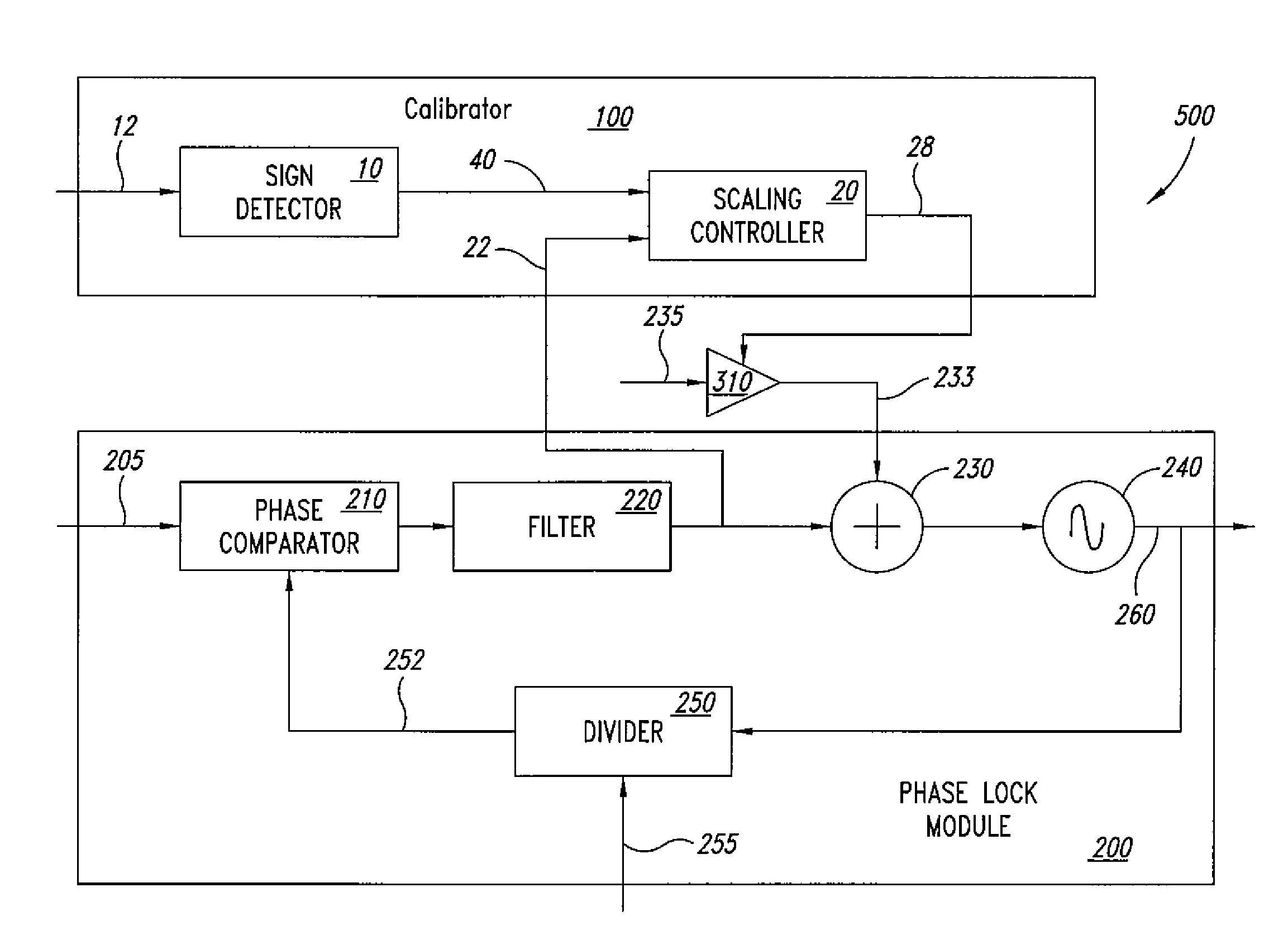
[0017]An embodiment may operate during normal operation of a phase locked loop without requiring dedicated time periods for calibration or a dedicated modulation signal. An embodiment may be independent of the spectral content of the modulation signal, such that different modulation signals can be applied without having to redesign the calibration scheme to ensure stability. This is beneficial in current communication environments where manufacturers of communications equipment are seeking to provide multi-mode equipment capable of operating in accordance with a variety of communication standards such as GSM, Bluetooth™, DECT, and UMTS. Furthermore, an embodiment may readily be implemented in either analog or digital hardware or in software.
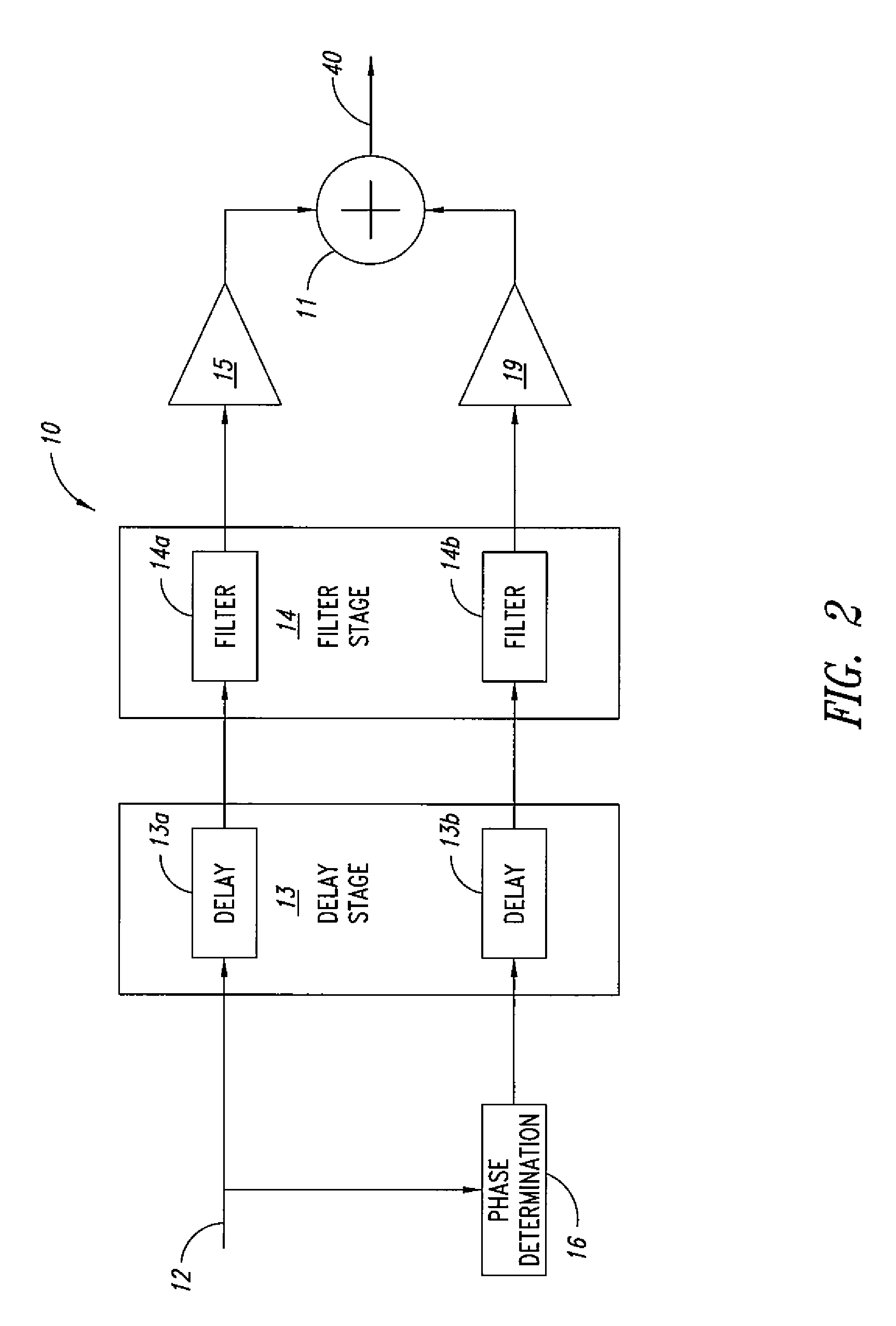
[0032]In such a phase locked loop, the delay introduced by the delay stage of the sign detector may correspond to a delay between a change in the modulation signal and a consequent change in the error signal. In this way, any difference between the delay in controlling the modulation signal in the apparatus and the response time of the phase locked loop to the modulation signal can be fully or partially compensated for.

Problems solved by technology

As the oscillator is typically an analogue circuit, the loop performance is susceptible to variations in analogue circuit characteristics, due to, for example, temperature or voltage changes or manufacturing process spread, which lead to variations in oscillator gain.
However, variations in oscillator gain will lead to variations in the modulated carrier signal.
However, if the oscillator gain is too high, high frequencies of the modulation signal are amplified too much, and if the oscillator gain is too low, high frequencies of the modulation signal are amplified too little.

Method used


Image

  • Phase locked loop calibration
  • Phase locked loop calibration
  • Phase locked loop calibration

Examples


Embodiment Construction

[0045]In the following description, numerous specific details are given to provide a thorough understanding of embodiments. The embodiments can be practiced without one or more of the specific details, or with other methods, components, materials, etc. In other instances, well-known structures, materials, or operations are not shown or described in detail to avoid obscuring aspects of the embodiments.

[0046]Reference throughout this specification to “one embodiment” or “an embodiment” means that a particular feature, structure, or characteristic described in connection with the embodiment is included in at least one embodiment. Thus, the appearances of the phrases “in one embodiment”“according to an embodiment” or “in an embodiment” and similar phrases in various places throughout this specification are not necessarily all referring to the same embodiment. Furthermore, the particular features, structures, or characteristics may be combined in any suitable manner in one or more embodi...


PUM


Abstract

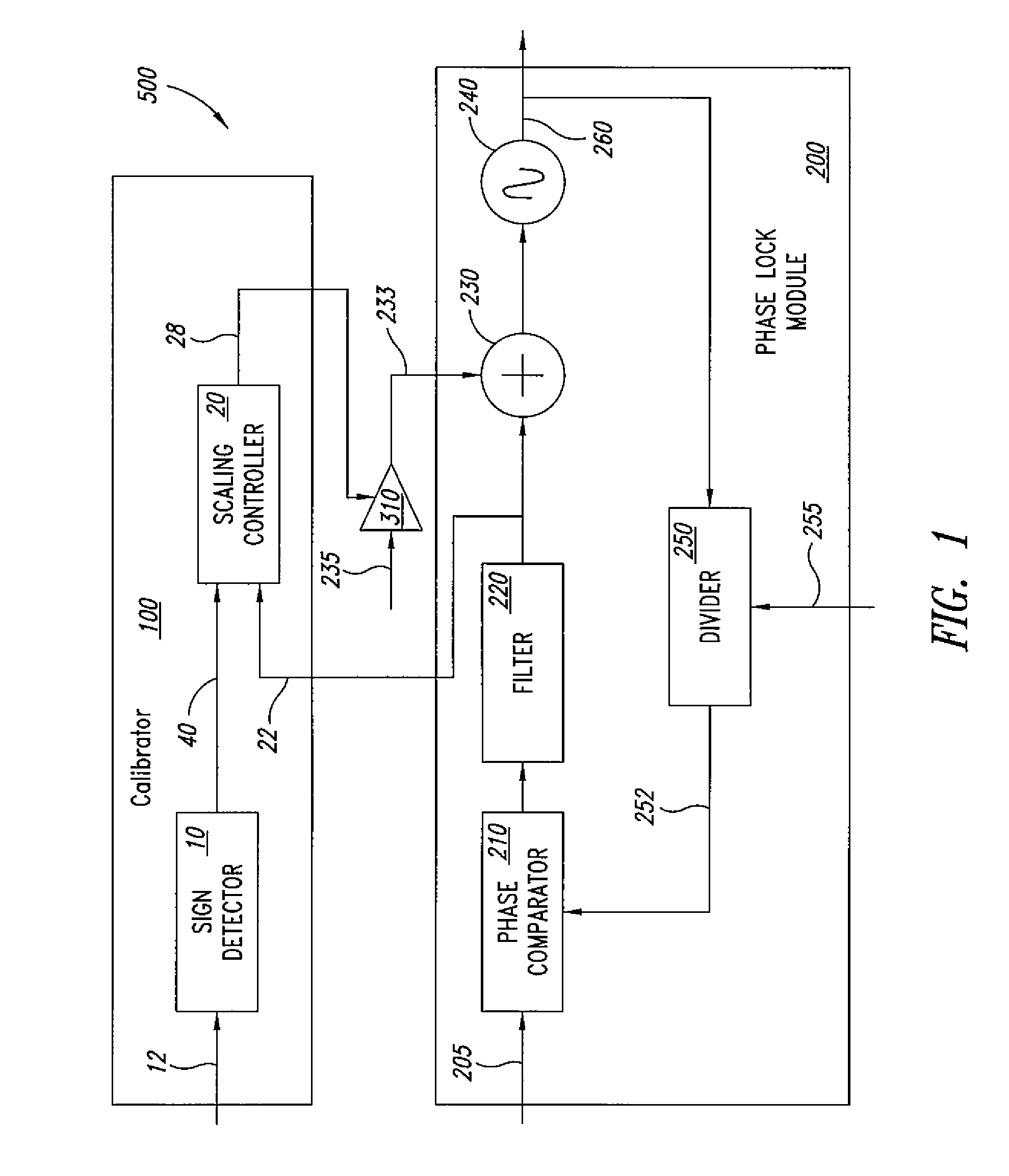
A method for controlling a modulation signal for modulating a phase locked loop. A scaling control signal for scaling the modulation signal is generated using the error signal of the phase locked loop. The scaling control signal is adjusted when the modulation signal and the phase of the modulation signal have the same sign.

Description

BACKGROUND[0001]1. Technical Field[0002]This disclosure relates to an apparatus and method for controlling a modulation signal for modulating a phase locked loop.[0003]2. Description of the Related Art[0004]Phase locked loops have a variety of applications, for example in frequency generation in wireless communication equipment. A basic phase locked loop comprises a variable frequency oscillator whose frequency and phase is controlled by an error signal, the error signal being generated by a phase detector that compares the phase of the oscillator output signal with the phase of a reference signal. The loop contains a low pass filter for filtering the error signal before it is applied to control the oscillator. Typically the oscillator operates at a higher frequency than the reference signal, and the loop includes a divider for dividing the oscillator output signal, such that the phase detector compares the divided signal with the reference signal.[0005]The loop performance depends,...

Claims


Application Information

Patent Timeline
Patent Type & Authority Applications(United States)
IPC IPC(8): H03D3/24
CPCH03C3/0925H03C3/095H03C3/0941
Inventor MARIE, HERVE
Owner TELEFON AB LM ERICSSON (PUBL)
Learn More