
Magnetic resonance imaging switching power amplifier system and methods

a switching power amplifier and magnetic resonance imaging technology, applied in the field of magnetic resonance imaging switching power amplifier system and methods, can solve the problems of electromagnetic interference, affecting the ability of the magnetic resonance imaging system to accurately interpret the radio frequency, affecting the associated cost of implantation, etc., to facilitate smoothing the pulse-width-modulated electrical power, facilitate the effect of pulse-width-modulated electrical power supply

Active Publication Date: 2020-03-10
GENERAL ELECTRIC CO
View PDF16 Cites 0 Cited by
  • Summary
  • Abstract
  • Description
  • Claims
  • Application Information

AI Technical Summary

Benefits of technology

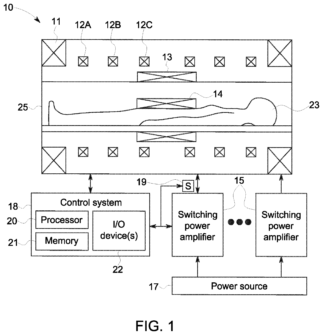
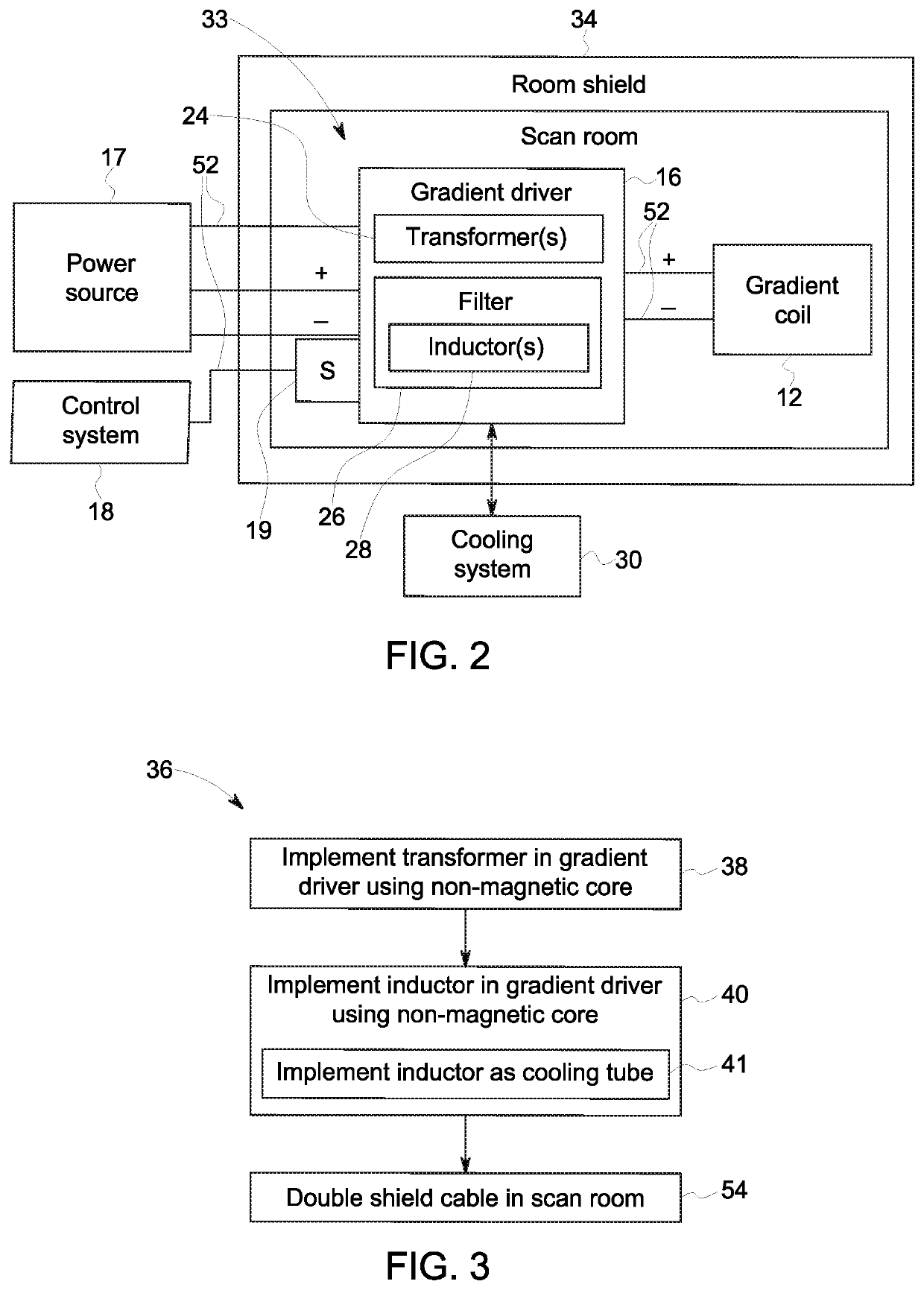
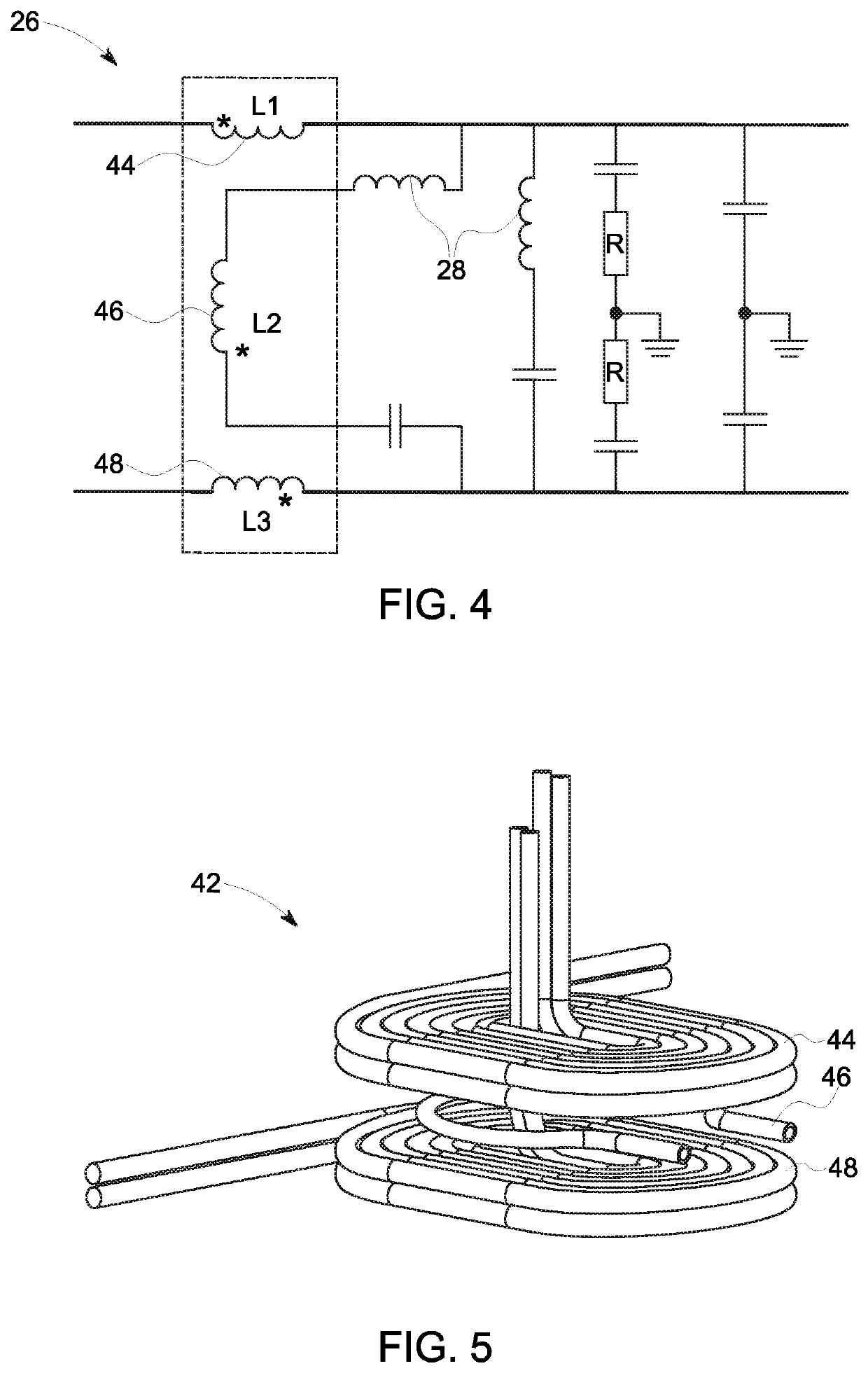
[0008]In another embodiment, this disclosure encompasses a method for implementing a magnetic resonance imaging system by electrically coupling a transformer with a non-magnetic core in a gradient driver between a switching stage and a filtering stage. This transformer facilitates supplying pulse-width-modulated electrical power to the filtering stage. The filtering stage facilitates smoothing the pulse-width-modulated electrical power and supplying it to a gradient coil. Within the filtering stage there may be inductors with non-magnetic cores. Additionally, there may be one or more inductors with hollow wire that enable fluid flow through within them.

Problems solved by technology

In other words, image capabilities of an MRI system may be affected by electromagnetic interference.
For example, when electrical current flows through a conductive material, an additional magnetic field may be generated that interacts with (e.g., distorts) the primary magnetic field, thereby affecting ability of the MRI system to accurately interpret the radio frequency signal received by the radio frequency receiver.
However, at least in some instances, implementing an MRI system in this manner may affect implantation associated cost, such as physical footprint of the MRI system.

Method used


Image

  • Magnetic resonance imaging switching power amplifier system and methods
  • Magnetic resonance imaging switching power amplifier system and methods
  • Magnetic resonance imaging switching power amplifier system and methods

Examples


Embodiment Construction

[0018]One or more specific embodiments of the present disclosure will be described below. These described embodiments are only examples of the presently disclosed techniques. Additionally, in an effort to provide a concise description of these embodiments, all features of an actual implementation may not be described in the specification. It should be appreciated that in the development of any such actual implementation, as in any engineering or design project, numerous implementation-specific decisions must be made to achieve the developers' specific goals, such as compliance with system-related and business-related constraints, which may vary from one implementation to another. Moreover, it should be appreciated that such a development effort might be complex and time consuming, but may nevertheless be a routine undertaking of design, fabrication, and manufacture for those of ordinary skill having the benefit of this disclosure.

[0019]When introducing elements of various embodiment...


PUM


Abstract

This disclosure regards a magnetic resonance imaging system including a scanner, and gradient drivers. The scanner is to be implemented within a scan room that is shielded from electromagnetic interference. Gradient coils are designed to create a linear gradient in the magnetic field generated in the scanner by a primary magnet. These coils are energized by gradient drivers. The gradient drivers use transformers and other electrical devices in a switching stage configured to generate pulse-width-modulated power. The transformers may have non-magnetic cores to facilitate implementing the gradient drivers within the scan room. The gradient drivers also use a filtering stage which uses inductors and other electrical devices to smooth the pulse-width-modulated power. The inductors within the filters may have non-magnetic cores to facilitate implementing the gradient driver within the scan room. Additionally, an inductor with a hollow wire may be used to circulate fluid to facilitate cooling the gradient driver.

Description

BACKGROUND[0001]This section is intended to introduce the reader to various aspects of art that may be related to various aspects of the present techniques, which are described and / or claimed below. This discussion is believed to be helpful in providing the reader with background information to facilitate a better understanding of the various aspects of the present disclosure. Accordingly, it should be understood that these statements are to be read in this light, and not as admissions of prior art.[0002]Generally, a magnetic resonance imaging (MRI) system may provide sub-surface imaging based on interaction of electromagnetic waves (e.g., radio frequency signal) and a magnetic field. For example, an MRI system may include a primary magnet that generates a primary magnetic field, one or more gradient coils that interact with the primary magnetic field to produce magnetic gradients, a radio frequency transmitter (e.g., coil or antenna) that outputs a radio frequency (RF) signal into ...

Claims


Application Information

Patent Timeline
Patent Type & Authority Patents(United States)
IPC IPC(8): G01R33/385G01R33/36G01R33/422
CPCG01R33/36G01R33/3852G01R33/422G01R33/3856G01R33/3614A61B5/055H03F3/217
Inventor WANG, RUXILIU, XIAOHUPENG, HANTAO, FENGFENGSABATE, JUAN ANTONIO
Owner GENERAL ELECTRIC CO
Learn More