
Apparatus and method for surface finishing cured concrete

a technology of concrete floor and surface finishing, which is applied in the direction of grinding heads, manufacturing tools, and ways, can solve the problems of insufficient removal of certain defects, inability to meet the needs of business owners, and inability to adequately remove defects, etc., to facilitate the installation of vacuum tubes, facilitate the removal and replacement, and improve containment

Inactive Publication Date: 2009-07-30
COPOULOS PAUL
View PDF32 Cites 32 Cited by
  • Summary
  • Abstract
  • Description
  • Claims
  • Application Information

AI Technical Summary

Benefits of technology

[0012]The annular pan has angle-shaped brackets secured thereon, each of which is dimensioned to receive a leading edge of the blades, thereby removably securing the pan to the blades. The angle-shaped brackets have a horizontal member and the leading edges of the blades are received by the angle-shaped brackets and are disposed in contact with the angle-shaped brackets during rotation of the blades, such that the horizontal member prevents vertical separation of the annular pan from the blades.
[0014]In another alternate embodiment, the annular pan further may selectively comprise a bottom surface with a shallow depression therein, wherein the first portion of the hook-and-loop fastener is secured within the shallow depression. This configuration prevents lateral movement of the abrading pad under forces during abrasion of a concrete surface.
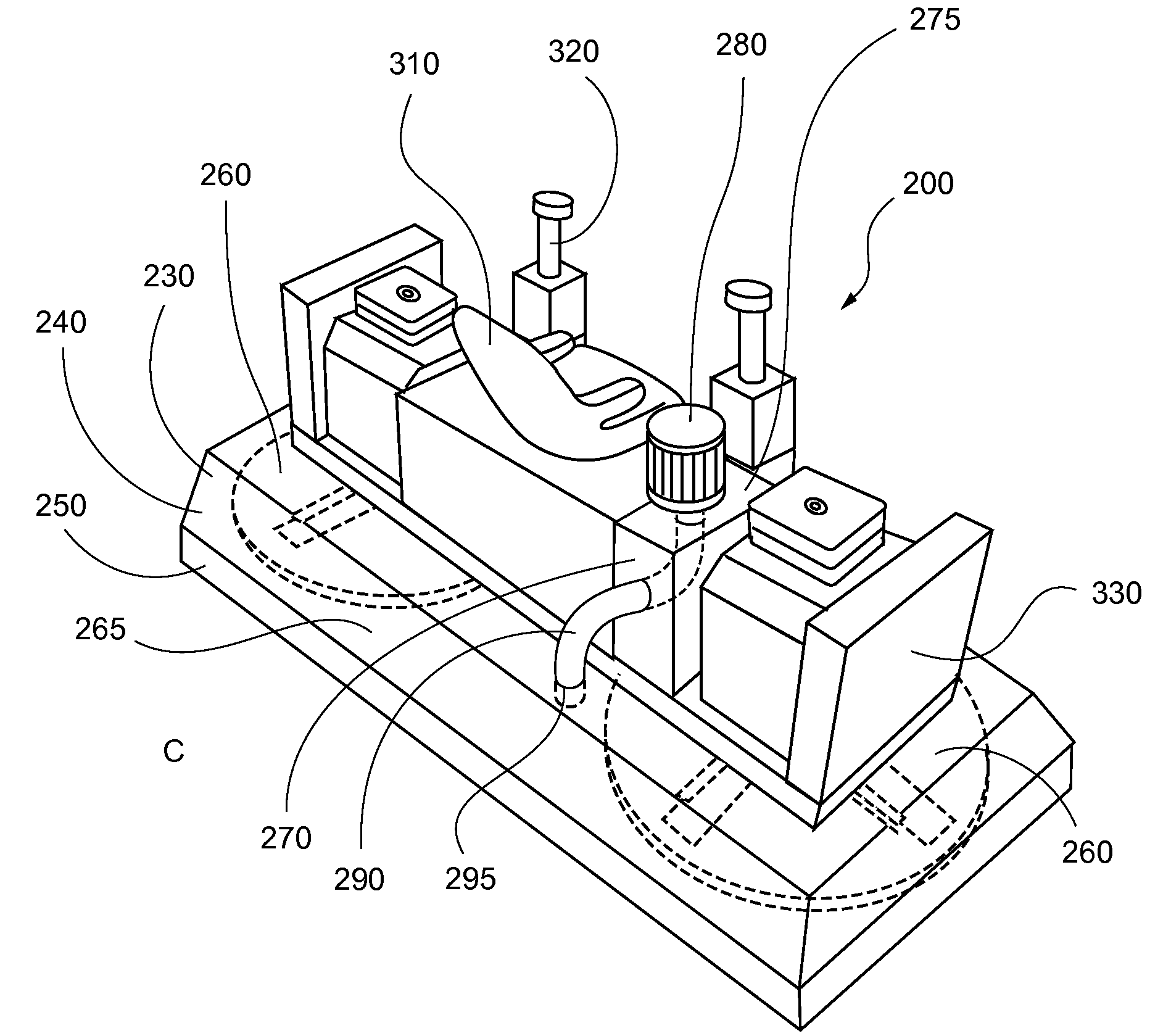
[0016]In still another alternate embodiment, the concrete finishing trowel comprises a shroud that encloses the abrading apparatuses to form a contained space. The shroud has a rigid upper section and a flexible lower section. The flexible lower section loosely forms a seal against a ground surface during operation of the concrete finishing trowel, thereby reducing the formation of clouds of dust from the detritus formed during abrasion of the concrete surface. In addition to containment by the shroud, the abrading apparatus may further comprise a vacuum system in fluid communication with a contained space within said shroud, thereby removing the abraded dust, passing it through a filter and allowing clean air to exit the filter. In this fashion, dust is minimized, reducing subsequent cleanup and health hazards.
[0019]The shroud has a rigid upper section to facilitate installation of the vacuum tube that provide fluid communication from the vacuum system to the contained space, and a flexible lower section that forms a loose seal against the concrete surface being finished, thereby retaining particulate matter and preventing same from forming clouds of dust particles.
[0020]More specifically, the present invention is a concrete finishing apparatus comprising abraders for finishing a concrete surface, the abraders being secured to the bottom surface of one or more annular pans via cooperative hook-and-loop fasteners, such as VELCRO, either directly or within depressions in the bottom surface. First halves of the cooperative hook-and-loop fasteners are secured to the bottom surface of the annular pans, either directly or within the depressions, and second halves of the cooperative hook-and-loop fasteners are secured to the individual abraders. This facilitates ready removal and replacement of the abraders. The use of depressions provides a slight recess for the abraders and improves containment thereof when the abraders subject to lateral forces during concrete finishing operations.

Problems solved by technology

Defects or imperfections in a concrete floor surface are unacceptable to most business proprietors and therefore must be removed.
Buffing techniques involve very little removal of concrete from the surface of fully cured concrete and therefore imperfections may remain.
Grinding of the surface has been employed, however, current practices do not adequately removing certain defects, such as a shoe imprints in the concrete surface, do not produce as flat a surface as the owner may want, cannot be made as flat as desired due to exposing aggregate and take too much time, which is almost always a negative from the owner's viewpoint.
However, even this prior practice does not achieve the desired smooth glossy finish.
This last mentioned procedure does produce a somewhat shiny surface but not the degree of gloss desired by the owners of the facilities and it does not remove surface defects or blemishes such as battery acid spills, oil and the like or surface irregularities such as foot prints which may have been pressed into the surface before the concrete had completely cured, and which, if not removed, will adversely affect the surface appearance even though polished.

Method used


Image

  • Apparatus and method for surface finishing cured concrete
  • Apparatus and method for surface finishing cured concrete
  • Apparatus and method for surface finishing cured concrete

Examples


Embodiment Construction

[0055]In describing the preferred and alternate embodiments as illustrated in FIGS. 1-29, specific terminology is employed for the sake of clarity. The invention, however, is not intended to be limited to the specific terminology so selected, and it is to be understood that each specific element includes all technical equivalents that operate in a similar manner to accomplish similar functions.

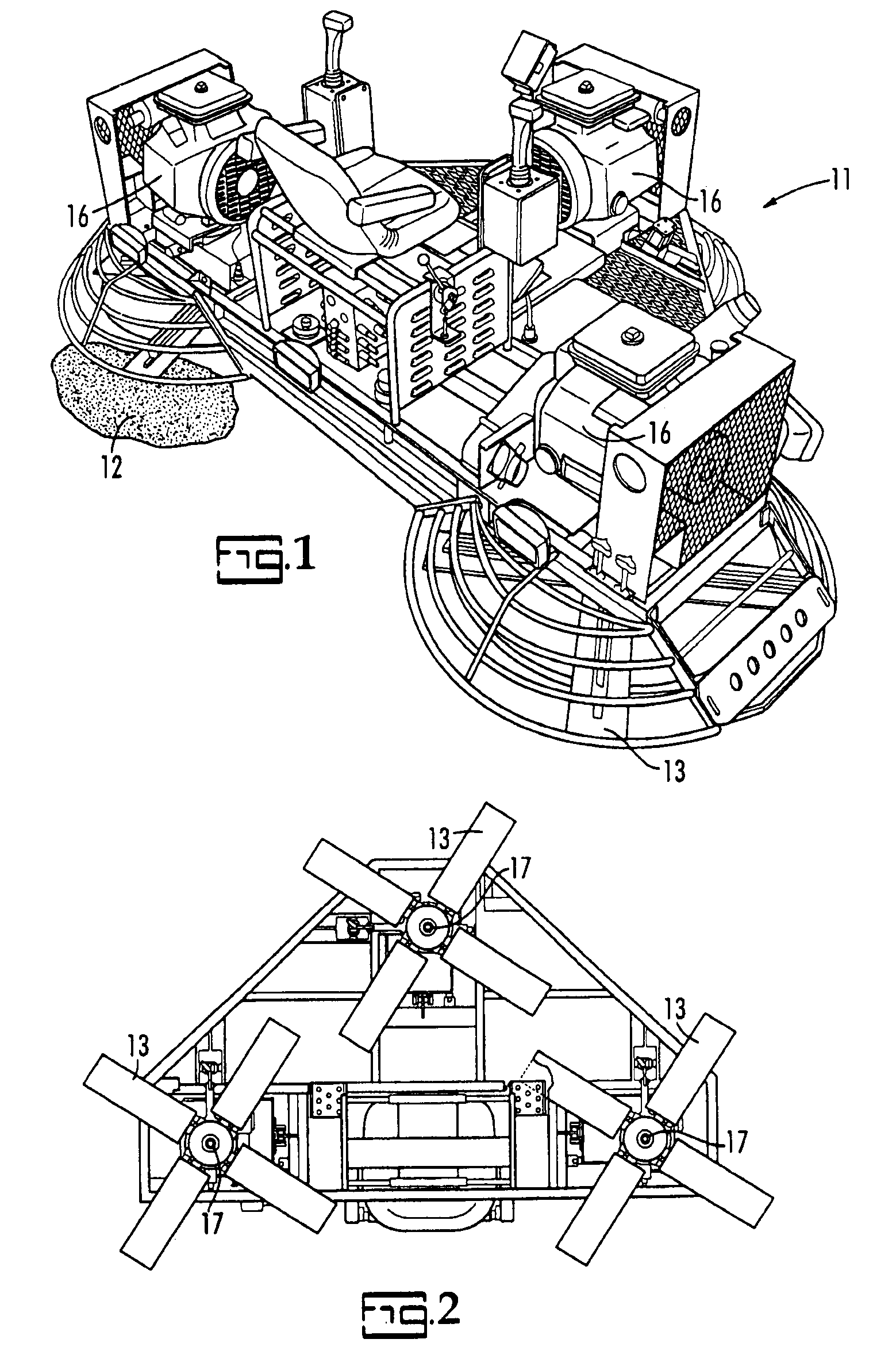
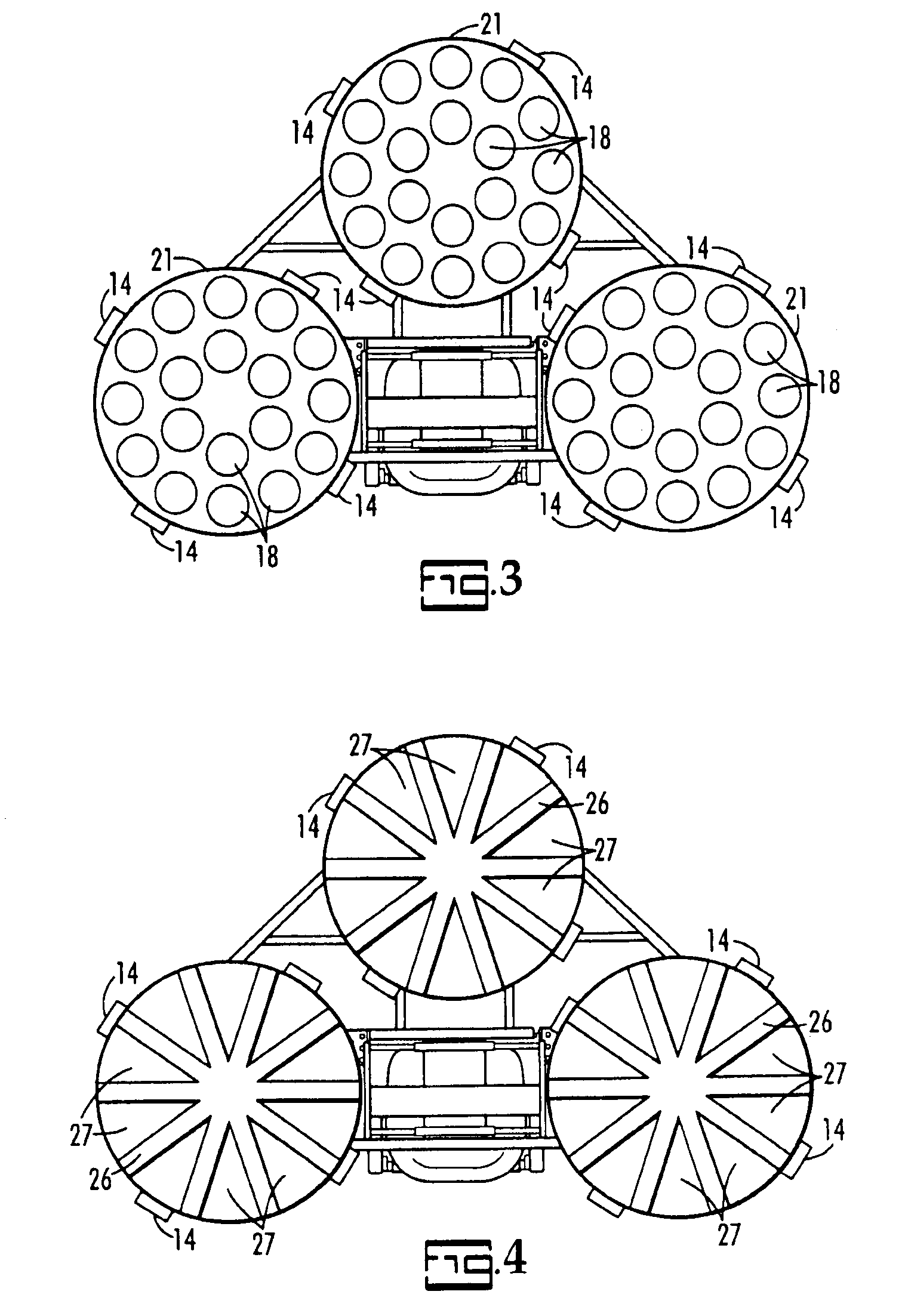
[0056]FIGS. 1 and 2 illustrate a riding trowel 11 used in smoothing concrete 12 which has not hardened. FIG. 2 is a bottom view of the riding trowel 11 showing three trowels 13 each having four blades 14. The trowels 13 are driven by three internal combustion engines 16 through vertical shafts 17, respectively. FIG. 3 shows three large pans 21 releasably secured to the blades 14 of the respective trowels 13 by suitable releasable fastening apparatus, not shown. Each pan 21 includes a relatively large number of relatively small diameter annular abraders 18, each of which is releasably fastened ...


PUM


Abstract

A method and apparatus for finishing cured concrete floors using a riding trowel to which large diameter pans are rotationally secured, the pans having abraders releasably secured to their undersides. The individual abraders are preferably individually removably secured to the pans by hook-and-loop fasteners, wherein the fasteners are selectively disposed on the flat bottom surfaces of the pans or within shallow depressions in the bottom surfaces of the pans. The riding trowel further comprises a vacuum system in fluid communication with a contained space formed by a shroud having a rigid upper portion and a flexible lower portion where it contacts the finished cured concrete floor surface.

Description

CROSS-REFERENCE TO RELATED APPLICATIONS[0001]The present application is a continuation-in-part application to non-provisional patent application Ser. No. 11 / 804,911, entitled “METHODS AND APPARATUSES FOR SURFACE FINISHING CURED CONCRETE”, filed on May 21, 2007 (claiming priority to provisional patent application Ser. No. 60 / 808,879 filed May 26, 2006), and to non-provisional continuation application Ser. No. 12 / 371,049, entitled “METHODS AND APPARATUSES FOR SURFACE FINISHING CURED CONCRETE”, filed on Feb. 13, 2009, and claims priority thereto and the full benefit thereof, the entire contents of the above applications being hereby incorporated by reference.FEDERALLY SPONSORED RESEARCH OR DEVELOPMENT[0002]NonePARTIES TO A JOINT RESEARCH AGREEMENT[0003]NoneREFERENCE TO A SEQUENCE LISTING[0004]NoneBACKGROUND OF THE INVENTION[0005]1. Technical Field of the Invention[0006]The present invention relates generally to concrete finishing apparatuses and more specifically to a concrete riding t...

Claims


Application Information

Patent Timeline
IPC IPC(8): E01C19/42
CPCB24B7/186E04F21/24B24B41/047E04F21/247
Inventor COPOULOS, PAUL
Owner COPOULOS PAUL
Learn More