Ophthalmic fluid delivery device and method of operation

a technology of ophthalmic fluid and delivery device, which is applied in the direction of eye treatment, inhalator, other medical devices, etc., can solve the problems of inefficient pharmacokinetics of the approach, insufficient ophthalmic drug delivery, and numerous problems

Inactive Publication Date: 2009-07-30
OPTIMYST SYST
View PDF3 Cites 99 Cited by
  • Summary
  • Abstract
  • Description
  • Claims
  • Application Information

AI Technical Summary

Benefits of technology

[0022]According to still another exemplary aspect, the present invention provides a method of preparing an ophthalmic fluid delivery device to deliver an ophthalmic fluid. The method includes selecting a reservoir containing the ophthalmic fluid from among a group of reservoirs containing a group of ophthalmic fluids. The reservoir is inserted into a cavity of the delivery device such that a contour on the reservoir aligns with a contour of the cavity, thereby maintaining the reservoir in a predetermined alignment and preventing an alignment other than the predetermined alignment.

Problems solved by technology

This means of ophthalmic drug delivery, however, has numerous problems.
This results in a brief period of massive over-dosage, which is quickly cleared by reflex lacrimation, blinking and nasolacrimal drainage, resulting in sub-therapeutic drug levels until the next medication application.
This approach represents very inefficient pharmacokinetics.
Attempts to prolong ocular contact time by various adaptations, such as the use of particulate suspensions, have led to other drawbacks including ocular irritation and excessively slow drug release.
Ointments and gels, though providing prolonged contact time, create obvious visual disturbances.
Further, local irritations and toxicities often result from the regular use of eye drops.
These situations vary widely depending on the pharmacologic agent, preservatives and other additives being used, but this is clearly a very non-physiologic and inefficient system of medication administration.
Chronic use of eye drops for such conditions as glaucoma and prolonged infections and inflammations can, in fact, cause substantial morbidity.
Additionally, serious and even fatal reactions to sympathomimetic and beta-adrenergic blocking agents have occurred as a result of systemic absorption of eye drops via nasolacrimal drainage.
Besides the above issues, there are a great many difficulties that patients experience with the mechanics of eye drop administration.
Elderly patients, the largest group of eye drop users, often have hand-eye coordination problems, tremors or arthritis, affecting the hands and / or the cervical spine, making eye drop administration difficult if not impossible.
Many users report that they have trouble keeping track of their regimens and often repeat doses or miss them entirely, suffering potential consequences in either event.
Further, pediatric patients, often unable to comprehend the reasons and benefits behind the administration of eye medication, often fight such application, typically resulting in underdosing due to the patient's attempts to prevent the eye drops from being administered, or overdosing, as a result of the administrator's attempt to ensure that sufficient dosage is being applied.
It is sometimes difficult to tell if the drop was properly instilled.
Direct application to the cornea can result in the drop “bouncing” from the eye with little or no benefit.
Also, many eye drop bottles are fabricated in such a way that loss is unavoidable as soon as the dropper is tilted.
All of the above represent needless waste of expensive medication (many glaucoma medications cost $70-$80 for a 5 ml bottle) and also increased the risk of side effects, while actually reducing the therapeutic benefit.
With an estimate of 25 million users of eye drops in the United States alone, the magnitude of the public health issue is considerable.
Which have inherent drawbacks relating to difficulties with calibrating the flow velocity, volume and particle size of the emitted spray.
Furthermore, the surface tension of a standard drop is a barrier to “mixing” and tear film incorporation.
In the professional office setting, this problem has led to many documented epidemics of viral keratoconjunctivitis.

Method used


Image

  • Ophthalmic fluid delivery device and method of operation
  • Ophthalmic fluid delivery device and method of operation
  • Ophthalmic fluid delivery device and method of operation

Examples


Embodiment Construction

[0106]Certain terminology is used in the following description for convenience only and is not limiting. As used herein, the term “distal” is meant to mean the discharge end of the inventive device and the term “proximal” is meant to mean the end of the inventive device held by user. The terminology includes the words above specifically mentioned, derivatives thereof and words of similar import. The embodiments illustrated below are not intended to be exhaustive or to limit the invention to the precise form disclosed. These embodiments are chosen and described to best explain the principle of the invention and its application and practical use and to enable others skilled in the art to best utilize the invention.

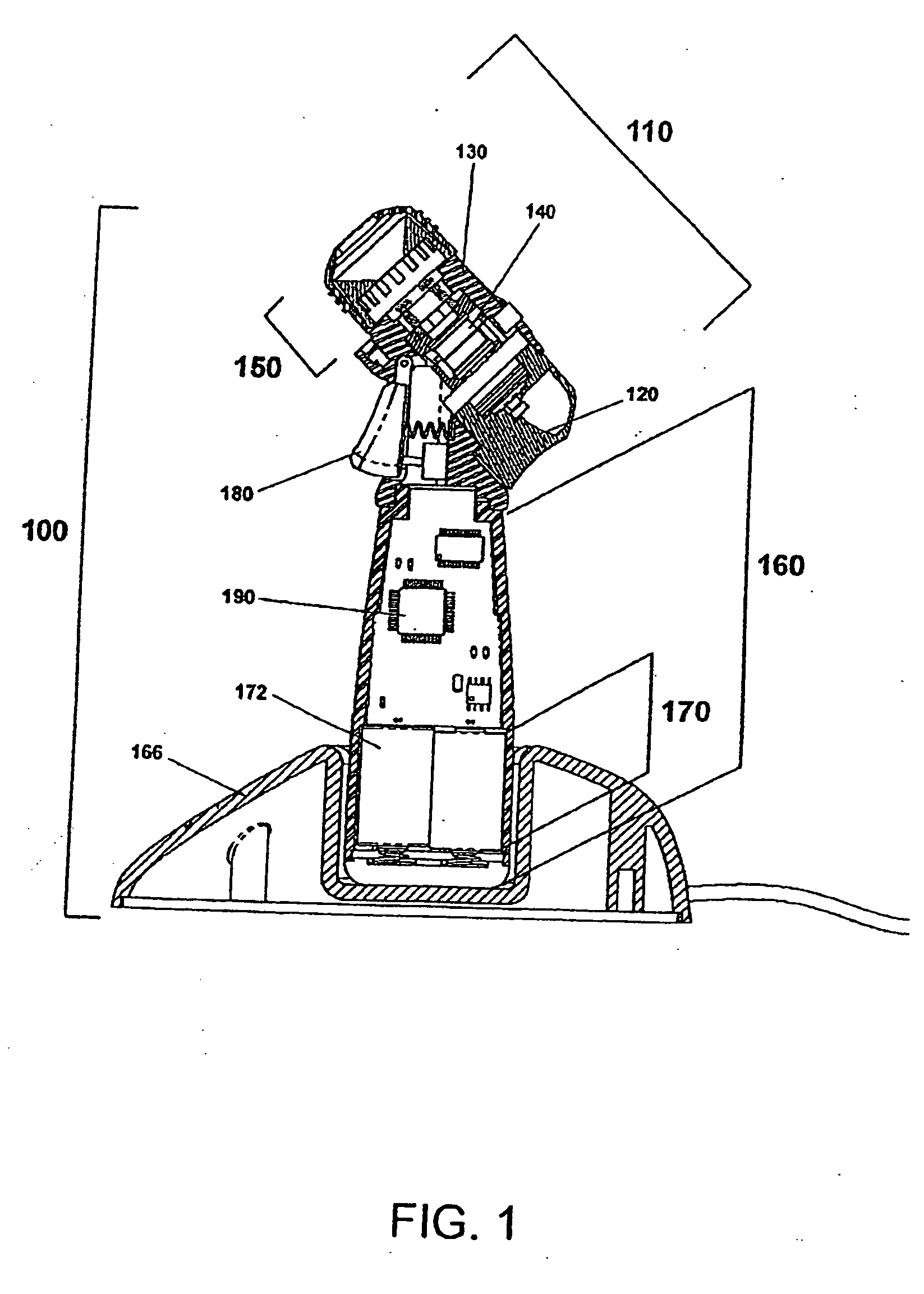
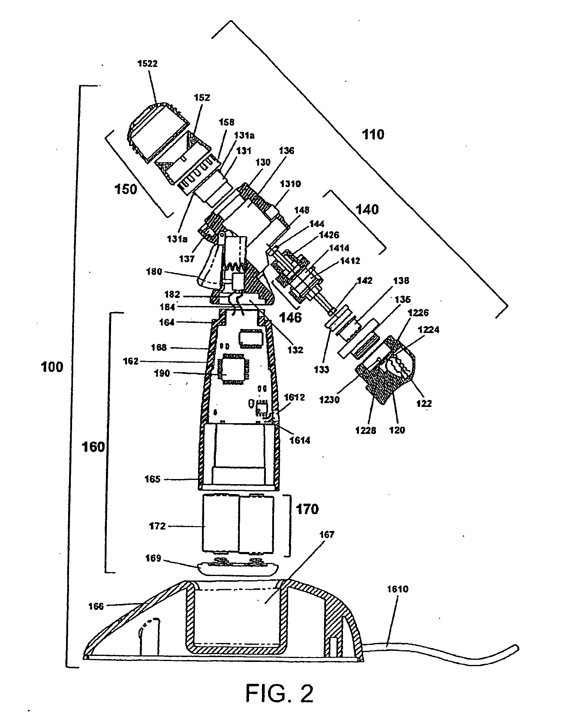
[0107]The present invention provides a novel device and method for ophthalmic drug delivery. In preferred embodiments, the present invention provides a small, hand-held, battery or ac powered device that nebulizes liquid eye medications into a fine mist. The mist from the de...


PUM


Abstract

An ophthalmic fluid atomizer configured to safely deliver an ophthalmic fluid, the ophthalmic fluid atomizer including a body having a proximal end, a distal end and a keyed surface contour, a reservoir connected to the body within a cavity of the body, wherein the reservoir contains an ophthalmic fluid disposed therein, wherein the keyed surface contour permits insertion of the reservoir into the cavity when the reservoir is in a predetermined orientation and prevents insertion into the cavity when the reservoir is not in the predetermined orientation. The atomizer further including a discharge plate disposed at the distal end, wherein the discharge plate includes a plurality of openings extending therethrough and a prime mover that transmits the ophthalmic fluid from the reservoir to the discharge plate, wherein transmission of the ophthalmic fluid across the discharge plate generates a plume of ophthalmic fluid along a direction directly toward the eye, wherein the plume of ophthalmic fluid travels unassisted from the discharge plate to the eye and at the eye has a momentum that has a magnitude that is insufficient to trigger at least one of an ocular blink reflex and a lacrimation reflex of the eye, wherein the plume of ophthalmic fluid contains an amount of ophthalmic medicine and the momentum of the plume is such that substantially all of the amount of ophthalmic medicine is received and retained by the eye. The atomizer further including a nozzle assembly attached to the body and a handle assembly comprising a handle, the handle assembly coupled to the nozzle assembly.

Description

CROSS REFERENCE TO RELATED APPLICATIONS[0001]The present application is a continuation of 1) Patent Cooperation Treaty Application No. PCT / US2008 / 0010503, filed on Jan. 25, 2008, which claims priority under 35 U.S.C. § 120 to both U.S. patent application Ser. No. 11 / 698,438, filed on Jan. 26, 2007, and U.S. patent application Ser. No. 11 / 698,647, filed on Jan. 26, 2007, 2) U.S. patent application Ser. No. 11 / 698,438, filed on Jan. 26, 2007 and 3) U.S. patent application Ser. No. 11 / 698,647, filed on Jan. 26, 2007, wherein U.S. patent application Ser. No. 11 / 698,438 and U.S. patent application Ser. No. 11 / 698,647 are each a continuation-in-part application of U.S. patent application Ser. No. 10 / 851,611, filed on May 20, 2004, which claims priority under 35 U.S.C. § 119(e) to both U.S. Provisional Application No. 60 / 485,305, filed on Jul. 3, 2003 and U.S. Provisional Application No. 60 / 471,883, filed on May 20, 2003, wherein each of the above mentioned Patent Cooperation Treaty, U.S. ...

Claims


Application Information

Patent Timeline
Patent Type & Authority Applications(United States)
IPC IPC(8): A61M11/00
CPCA61F9/0008A61M11/042A61M15/0065A61M15/0085A61M2205/18A61M2205/3306A61M2205/3386A61M2205/581A61M2205/583A61M2205/59A61M2205/8206A61M2205/8212A61M2205/8237A61M2209/086B05B1/14B05B11/0002B05B12/004B05B12/081B05B15/00B05B17/0607A61M11/005A61M11/065A61M15/0066A61M15/0071A61M15/008A61M15/0081A61M15/0083
Inventor COLLINS, JR., JAMES F.
Owner OPTIMYST SYST
Why Eureka
Try Eureka