Osteoporatic screw and expansion sleeve

a technology of expansion sleeves and osteoporation screws, which is applied in the direction of osteosynthesis devices, prostheses, ligaments, etc., can solve the problems of difficulty in maintaining the fixed position of pedicle screws in the vertebrae, complicated surgical procedures for bone screws, and the procedure of fusing vertebrae, etc., to facilitate the threading of the screw shaft

Inactive Publication Date: 2009-07-30
ANDERSEN BRUCE J +1
View PDF27 Cites 21 Cited by
  • Summary
  • Abstract
  • Description
  • Claims
  • Application Information

AI Technical Summary

Benefits of technology

[0005]The invention is a bone screw assembly with an apparatus for anchoring the screw assembly within a bone and a hollow core structure for injecting fluid material into bone. The device contains a cylindrical screw shaft with a cutting tip on one end and a blunt driving tip on the other end. The surface of the screw shaft contains a helical groove that facilitates threading the screw shaft into the bone once the cutting tip of the screw is within the surface of the bone.

Problems solved by technology

Placement of bone screws requires complicated and intricate surgical procedures.
Problems often arise with conventional pedicle screws and the procedure of fusing vertebrae.
The lack of structural integrity in the bone often causes difficulty in maintaining pedicle screws in a fixed position in the vertebrae.
Screws may work out of the vertebrae or crack and shatter regions of the vertebrae adjacent to the screw.

Method used


Image

  • Osteoporatic screw and expansion sleeve
  • Osteoporatic screw and expansion sleeve
  • Osteoporatic screw and expansion sleeve

Examples


Embodiment Construction

[0020]While the invention is susceptible of various modifications and alternative constructions, certain illustrated embodiments thereof have been shown in the drawings and will be described below in detail. It should be understood, however, that there is no intention to limit the invention to the specific form disclosed, but, on the contrary, the invention is to cover all modifications, alternative constructions, and equivalents falling within the spirit and scope of the invention as defined in the claims.

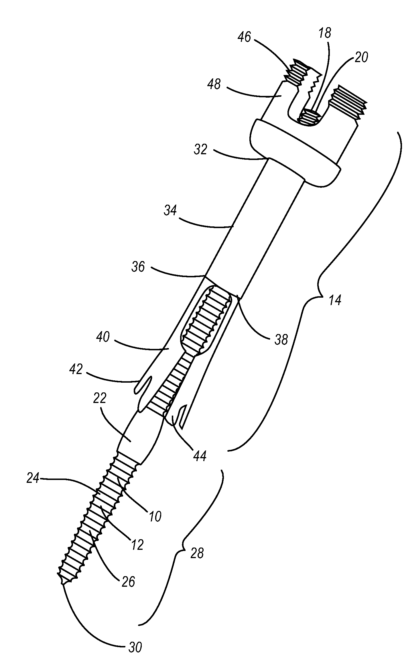
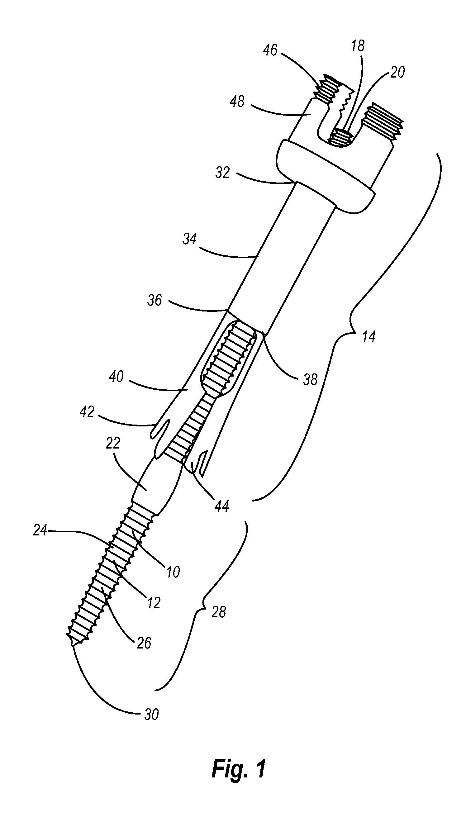
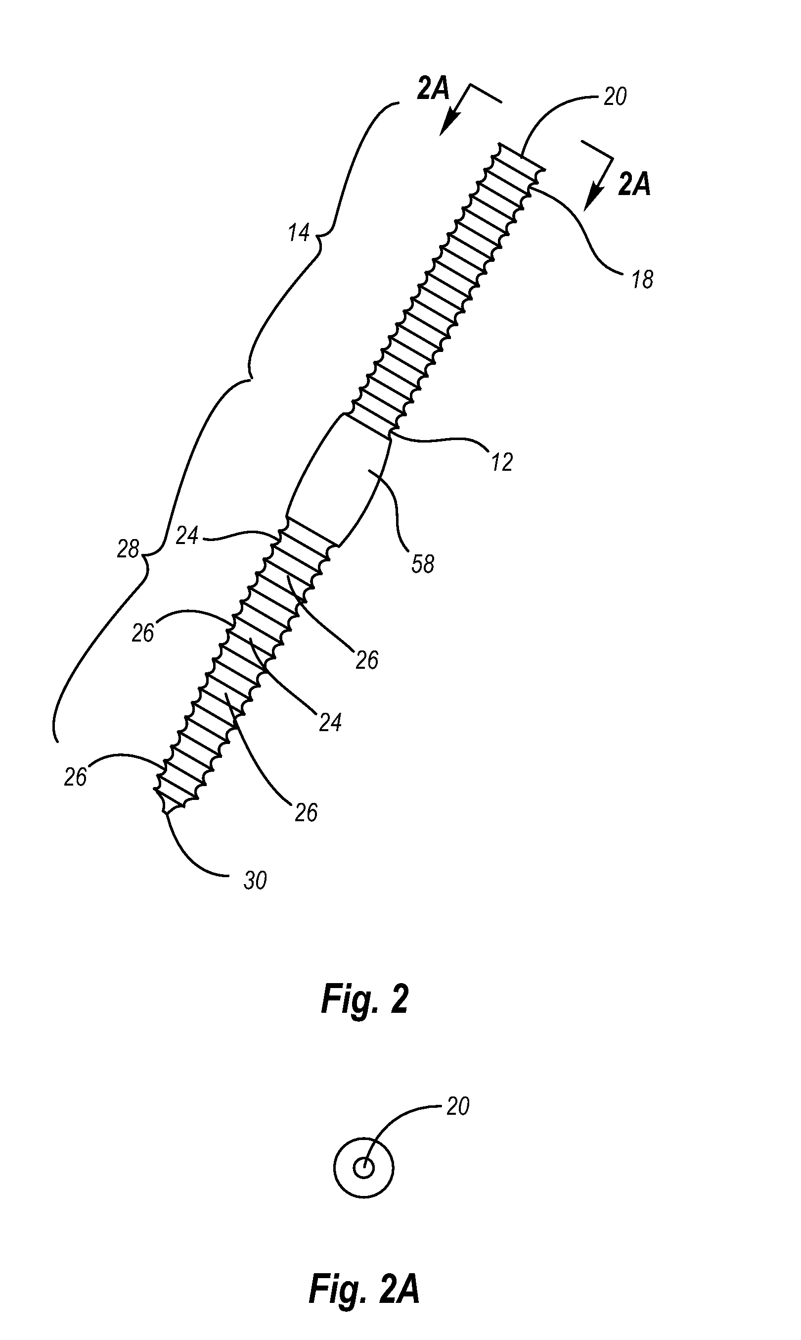
[0021]The field art related to bone screws, pedicle screws in particular, has seen a long felt and unresolved need for a bone screw that anchors within a vertebrae and stabilizes the vertebrae. Bone material in vertebrae is porous material, especially in elderly patients. Therefore, conventional pedicle screws often become dislodged or shatter bone material in the vertebrae due to lack of structural stability within the bone. When pedicle screws become dislodged in this manner, ad...


PUM


Abstract

The invention is a bone screw apparatus. The bone screw apparatus has two specialized functions for stabilizing the screw within a bone. The first is a mechanical structure that anchors the screw within a bone and the second is a structure that allows injection of bone cement through the screw assembly and into the interior structure of the bone. The anchoring mechanism functions by an expandable member that slides concentrically over the shaft of the screw. When the expandable member is forced over a portion of the screw shaft with an enlarged diameter, the expandable member extends radially from the screw shaft, and the bone screw is anchored to the interior structure of the bone. The injecting function of the bone screw apparatus functions through the use of a hollow core within the screw shaft. The hollow core of the screw shaft has an inlet at the top of the shaft and at least one outlet near the tip of the screw shaft. Once the screw shaft is inserted into the interior structure of a bone, bone cement may be injected into the inlet at the top of the screw shaft. The bone cement travels through the hollow core of the screw shaft and is extruded out the holes near the tip of the screw shaft. The bone cement fills the void spaces within the bone structure and strengthens the bone.

Description

FIELD OF THE INVENTION[0001]The invention relates generally to a bone screw assembly and more particularly to a bone screw with an anchoring apparatus and a passage for injecting material into a bone.BACKGROUND OF THE INVENTION[0002]Bone screws have been known to the medical field for some time. Bone screws are used to bind fractured bone or attach therapeutic implants to bone structure. Placement of bone screws requires complicated and intricate surgical procedures.[0003]Bone screws are common to spinal surgery in which adjacent vertebrae are linked together. The procedure of fusing vertebrae requires insertion of pedicle screws into the pedicle of vertebrae. Once the screws are set, separate hardware is used to link the screws in adjacent vertebrae together. The hardware is then tightened and the adjacent vertebrae are immobilized in relation to one another.[0004]Problems often arise with conventional pedicle screws and the procedure of fusing vertebrae. Vertebrae are porous bone,...

Claims


Application Information

Patent Timeline
Patent Type & Authority Applications(United States)
IPC IPC(8): A61B17/56A61B17/58
CPCA61B17/686A61B17/8685A61B17/7098A61B17/7032Y10S411/913
Inventor ANDERSEN, BRUCE J.ZIMMERMAN, CHRISTIAN G.
Owner ANDERSEN BRUCE J
Why Eureka
Try Eureka