Product Lifecycle Management Method and Apparatus

a product lifecycle management and product technology, applied in the direction of program control, total factory control, instruments, etc., can solve the problems of flawed design and instantiation engineering or expert working in a first system may not recognize when, and the process of completely designing all aspects of a manufacturing process is extremely complex

Inactive Publication Date: 2009-07-30
ROCKWELL AUTOMATION TECH
View PDF12 Cites 17 Cited by
  • Summary
  • Abstract
  • Description
  • Claims
  • Application Information

AI Technical Summary

Benefits of technology

[0013]It has been recognized that where different systems are used to specify different information types needed to together define a manufacturing system, inconsistencies between specified information of the different types can be automatically identified and notice of the inconsistencies can be provided so that the inconsistencies can be eliminated. Moreover, it has been recognized that where inconsistencies occur between different information types, a system can automatically identify possible solutions for eliminating the inconsistencies and those solutions can either be suggested to engineers or experts or may be implemented automatically, in at least some embodiments.
[0014]To facilitate the process of recognizing information inconsistencies, information in the different systems is stored as objects and the objects or information in the objects specified using the different systems can be compared to identify inconsistencies. For instance, in the case of a mechanical specifying system and a control specifying system, the mechanical system may include a library of mechanical device objects that can be used to define a manufacturing cell and the control system may include a separate set of add on instructions (AOI) for each of the device objects that specifies actions that each device can perform along with code or information useable to generate code for controlling the associated device. Here, where an AOI is used to specify logic and there is no associated device in a specified cell or where an AOI action is specified and associated code is provided where the action is not specified for a corresponding cell, an inconsistency can readily be identified and communicated to a mechanical engineer so that the inconsistency can be eliminated.

Problems solved by technology

The process of completely designing all aspects of a manufacturing process is extremely complex and requires input from many different people that have varying skill sets.
While the manufacturing line design process described above is becoming ubiquitous, unfortunately identification of inconsistencies between different information types and communication of those inconsistencies to others working on designing and instantiating a manufacturing process is flawed for at least two reasons.
First, an engineer or expert working in a first system may not recognize when information specified using the first system is inconsistent with information specified using one or more of the other systems.
Here, all of the engineers and experts may simply miss an inconsistency between the specified information of different types and the error may only be able to be recognized far down the design line at a time when it is far more complex and expensive to eliminate the inconsistency from the system.
Second, even when an engineer or expert recognizes an inconsistency, the engineer may fail to provide notice to all of the others working on the system that have a need to know about the inconsistency or one or more of the others that receive notice may not address the inconsistency when the notice is received.
The two flaws with the system described above are exacerbated in cases where the different specifying systems are used in parallel so that different engineers and experts are specifying information simultaneously in many cases that can lead to inconsistencies.
In addition, the flaws are further exacerbated in cases where more than one engineer or expert may be working on a single system type to specify required information during a complex or large design case.
For instance, in some cases two or more mechanical engineers may work simultaneously or in series to design a cell or related cells and one engineer may be unaware of what the other is doing so that inconsistencies cannot be easily identified.

Method used


Image

  • Product Lifecycle Management Method and Apparatus
  • Product Lifecycle Management Method and Apparatus
  • Product Lifecycle Management Method and Apparatus

Examples


Embodiment Construction

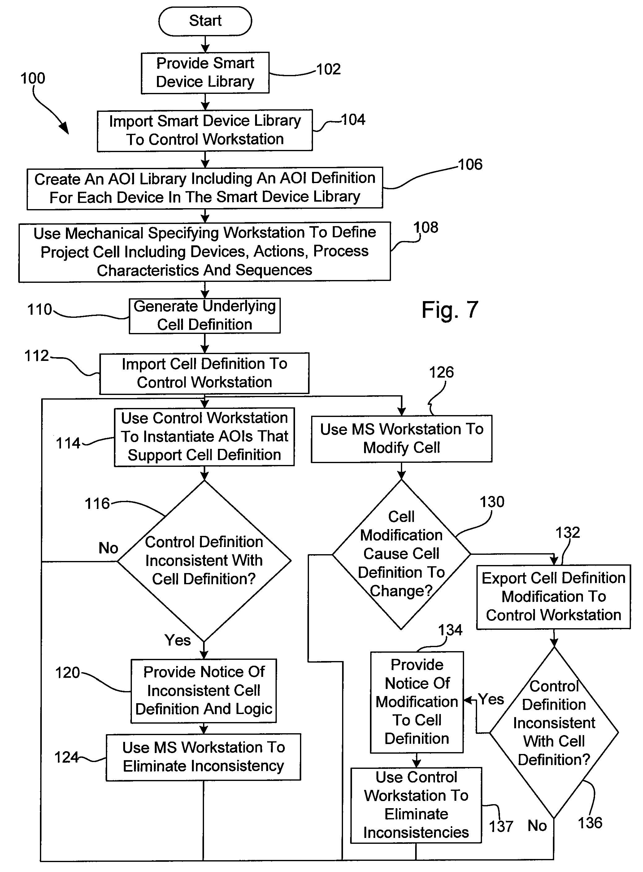
[0044]Referring now to the drawings wherein like reference numerals correspond to similar elements throughout several views and, more specifically, referring to FIG. 1, the present invention will be described in the context of an exemplary design system 10 that includes a mechanical specifying system 12, a control specifying system 14 and a communication network 16. Unless indicated otherwise, hereinafter a user of system 12 will be referred to generally as a mechanical engineer and a user of system 14 will be referred to as a control engineer. System 12 includes a mechanical specifying workstation 18, a server 20 and a database 22. Workstation 18 includes a processor based computer, an output devices such as a flat panel display screen and an input device such as a keyboard, mouse device, trackball, etc. Server 20 runs programs that enable a user of workstation 18 to define products to be manufactured and thereafter to define a manufacturing process for producing the designed produ...


PUM


Abstract

A method for synchronizing activities during design of an industrial automated system wherein the automated system includes a plurality of different features and the design of the automated system requires at least first and second different information types, the method comprising the steps of using a first software program to specify a first type system definition including a set of first information type instances corresponding to the automated system, after the first type system definition has been specified, using a second software program to specify a second type system definition including a set of second information type instances corresponding to the automated system, after the second type system definition has been specified, comparing the first and second system definitions to identify system features supported by only one of the first and second type system definitions and where only one of the first and second type system definitions supports a system feature, the second software program providing notice to the first software program indicating that the first and second type system definitions are imperfectly correlated.

Description

CROSS-REFERENCE TO RELATED APPLICATIONS[0001]Not applicable.STATEMENT REGARDING FEDERALLY SPONSORED RESEARCH OR DEVELOPMENT[0002]Not applicable.BACKGROUND OF THE INVENTION[0003]The present invention relates to systems for designing and generating control code for automated manufacturing systems and more specifically to a system for synchronizing design efforts among various designers using different software programs that specify different parts of the manufacturing system.[0004]The process of completely designing all aspects of a manufacturing process is extremely complex and requires input from many different people that have varying skill sets. To this end, an exemplary design process often starts with a mechanical engineer using a CAD software program at one workstation to design a product to be manufactured.[0005]Once the product is completely specified, a second mechanical engineer that specializes in designing mechanical systems for manufacturing products receives the product...

Claims


Application Information

Patent Timeline
Patent Type & Authority Applications(United States)
IPC IPC(8): G06F17/00
CPCG05B19/4188G05B15/02G06Q10/0631Y02P90/02
Inventor MORSE, RICHARD A.WEBER, JASON
Owner ROCKWELL AUTOMATION TECH
Why Eureka
Try Eureka