Turbo compressor and refrigerator

Active Publication Date: 2009-08-06
DAIKIN IND LTD
View PDF13 Cites 21 Cited by
  • Summary
  • Abstract
  • Description
  • Claims
  • Application Information

AI Technical Summary

Benefits of technology

[0026]By adopting such a configuration, in the present invention, the refrigerant which has been discharged and removed from the flow path can be reused without being discarded.
[0027]According to the present invention, in a turbo compressor including an impeller which is rotationally driven, and a flow path in which the impeller is provided, and through which gas flows, and sucking and compressing the gas in the flow path, a configuration in which the turbo compressor includes a fluid discharge device which dis

Problems solved by technology

In a compressor, when a compression ratio increases, the discharge temperature of the compressor becomes high and the volumetric efficiency thereof degrades.
As a result, an excessive power load acts on the impeller.
Fatigue breaking of the impeller by liquid colliding may occur b

Method used


Image

  • Turbo compressor and refrigerator
  • Turbo compressor and refrigerator
  • Turbo compressor and refrigerator

Examples


Embodiment Construction

[0034]Hereinafter, an embodiment of the present invention will be described with reference to the drawings.

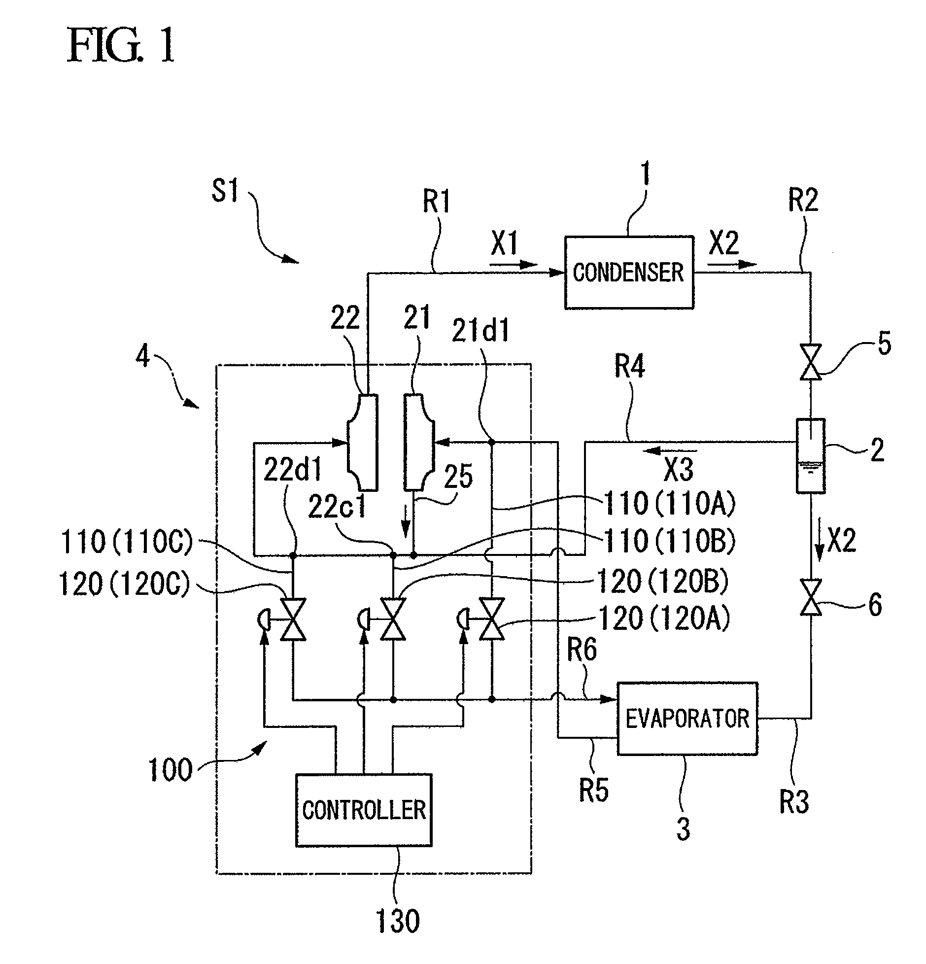
[0035]FIG. 1 is a block diagram showing a schematic configuration of a turbo refrigerator (refrigerator) S1 in this embodiment.

[0036]The turbo refrigerator S1 in this embodiment is installed in buildings or factories in order to generate, for example, cooling water for air conditioning. As shown in FIG. 1, the turbo refrigerator S1 includes a condenser 1, an economizer 2, an evaporator (fluid discharge unit) 3, and a turbo compressor 4.

[0037]In the condenser 1, a compressed refrigerant gas X1 that is a refrigerant compressed in a gaseous state is supplied thereto, and the compressed refrigerant gas X1 is cooled and liquefied to form a refrigerant fluid X2. The condenser 1, as shown in FIG. 1, is connected to the turbo compressor 4 via a pipe R1 through which the compressed refrigerant gas X1 flows, and is connected to the economizer 2 via a pipe R2 through which the refrigerant...


PUM


Abstract

A turbo compressor includes an impeller which is rotationally driven, and a flow path in which the impeller is provided, and through which gas flows, the turbo compressor sucking and compressing the gas in the flow path. The turbo compressor further includes a fluid discharge device which discharges a liquid in the flow path on the upstream side of the impeller.

Description

BACKGROUND OF THE INVENTION[0001]1. Field of the Invention[0002]The present invention relates to a turbo compressor capable of compressing a liquid by a plurality of impellers, and a refrigerator including the turbo compressor.[0003]Priority is claimed on Japanese Patent Application No. 2008-027071, filed Feb. 6, 2008, the content of which are incorporated herein by reference.[0004]2. Description of the Related Art[0005]As refrigerators which cool or freeze objects to be cooled, such as water, a turbo refrigerator or the like including a turbo compressor which compresses and discharges a refrigerant by impellers is known.[0006]In a compressor, when a compression ratio increases, the discharge temperature of the compressor becomes high and the volumetric efficiency thereof degrades. Thus, in the turbo compressor included in the above-mentioned turbo refrigerator or the like, a refrigerant may be compressed in a plurality of stages. For example, a turbo compressor which includes two c...

Claims


Application Information

Patent Timeline
IPC IPC(8): F25B1/10
CPCF04D17/122F04D29/705F04D25/06F04D29/706F25B1/053F25B1/10F25B2400/23F25B2500/28F25B41/22
Inventor SUGITANI, NORIYASU
Owner DAIKIN IND LTD
Why Eureka
Try Eureka