
Vessel Including Automatic Ballast System Using Tubes

a technology of automatic ballast and vessel, which is applied in the field of vessels, can solve the problems of unnecessarily spending of exchange of pipes, excessive working expenses, and unnecessary spending of exchange pipes, and achieve the effects of reducing the impact of vessel hull, reducing the cost of vessel repair and maintenance, and contaminating seawater or other problems

Inactive Publication Date: 2009-08-06
KIM YONG KYUNG
View PDF3 Cites 3 Cited by
  • Summary
  • Abstract
  • Description
  • Claims
  • Application Information

AI Technical Summary

Benefits of technology

[0021]According to the present invention so configured, all the objects of the present invention can be achieved. By using the above configuration, buoyancy is applied not to the outer shell of a vessel but to the outer shell of the cargo tank of the vessel. Thus, since a desired ballast draft line can be easily ensured, a variety of devices for introducing or discharging ballast do not have to be used. Further, since seawater is not confined in the vessel, the seawater can be freely introduced and discharged while the vessel is sailing, whereby the contamination of seawater or adverse effects due to the transport of microorganisms from one port to another can be minimized. Furthermore, since the area where seawater is brought into direct contact with the inner shell of the vessel is very small, vessel repair and maintenance costs caused by the corrosion or painting operation of a vessel hull can be markedly reduced. Moreover, impact on the vessel hull can be reduced even when the vessel is damaged at sea.
[0022]The above effects will be again described in detail. That is, the most advantageous effect of the present invention is that the restoration and survival chance of the vessel hull can be kept at a higher level even when the vessel is damaged. In a case where an empty vessel is damaged, impact applied to the vessel hull is minimized because seawater can be freely introduced and discharged. In such a case, if compressed air is introduced into air tubes and kept at a desired level, the draft line of the vessel hull is not substantially changed. Obviously, the draft line is kept substantially identical to a case where the vessel hull is not damaged.
[0023]Further, even if a vessel is damaged at a fully loaded state, the impact applied to the hull can be absorbed by compressed air tubes. Therefore, damage to the vessel hull is minimized and seawater is not substantially introduced into the vessel. There is a great advantage in maintaining the survival and restoration of the vessel hull. That is, the possibility that the vessel overturns or sinks can be greatly reduced.
[0024]Another effect of the present invention is that there is no contamination of seawater caused by ballast. Since seawater is not confined as ballast, it can be freely introduced and discharged. Thus, there is an advantage in that microorganisms in other regions have no influence on the marine environment at a specific region. For example, the present invention satisfies the requirements provided in the National Invasive Species Act (P.L. 104-332) that was enacted for preventing proliferation and invasion of organic matters into U.S. territorial waters via ballast of commercial vessels. Further, the present invention also solves many problems related to the above requirements.
[0025]A further effect of the present invention is that the cost of vessel repair is greatly reduced because the corrosion and painting operation of the vessel hull are markedly decreased. The reason is that since the seawater tubes prevent the vessel hull from being brought into contact with the seawater, the interior of the ballast tank can be easily kept dry.
[0026]A still further effect of the present invention is that costs due to the operation of the ballast system can be reduced. Since the ballast tank can be freely opened and closed, a need for the ballast system is reduced, and thus, the operation costs of the ballast system are similarly reduced.

Problems solved by technology

Meanwhile, mandatory rules for double-hulled vessels have been recently introduced due to serious marine pollution caused by the collision or stranding of vessels.
However, such a system has a problem that excessive working expenses due to frequent power loss, pump damage, the exchange of pipes and the like should be unnecessarily spent.
At this time, there is a problem that the microorganisms included in the seawater may cause serious changes in the ecological system of microorganisms living around the port of discharge.
A variety of suggestions for solving the aforementioned problem have been provided, but they are relatively ineffective.
The ballast tank is easily corroded on its surface exposed to the seawater filled therein, which may make the hull weaker.
Due to this corrosion, the painting operation of the interior of the vessel and the exchange of steel plates of the vessel should be frequently performed, which may cause a great deal of repair and maintenance costs.
Further, the seawater contaminated by the corrosion may have a serious negative influence on the marine environment.
In particular, it is very important that when the vessel is damaged, conventional methods cannot ensure the restoration and survival chance of the damaged vessels.
However, even in such a case, the restoration and survival chance of the vessel are very low, and thus, the resultant damage to the vessel is unimaginably serious.

Method used


Image

  • Vessel Including Automatic Ballast System Using Tubes
  • Vessel Including Automatic Ballast System Using Tubes
  • Vessel Including Automatic Ballast System Using Tubes

Examples


Embodiment Construction

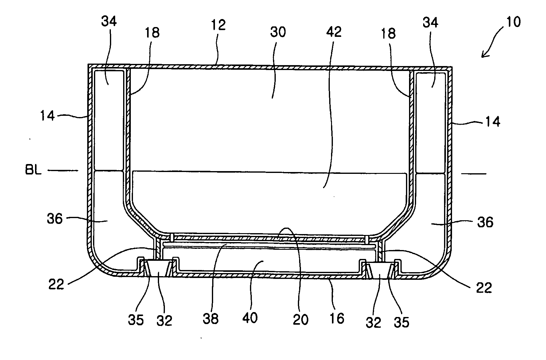
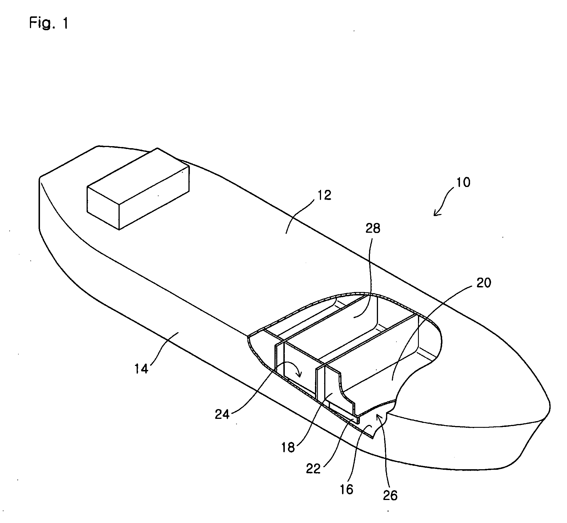
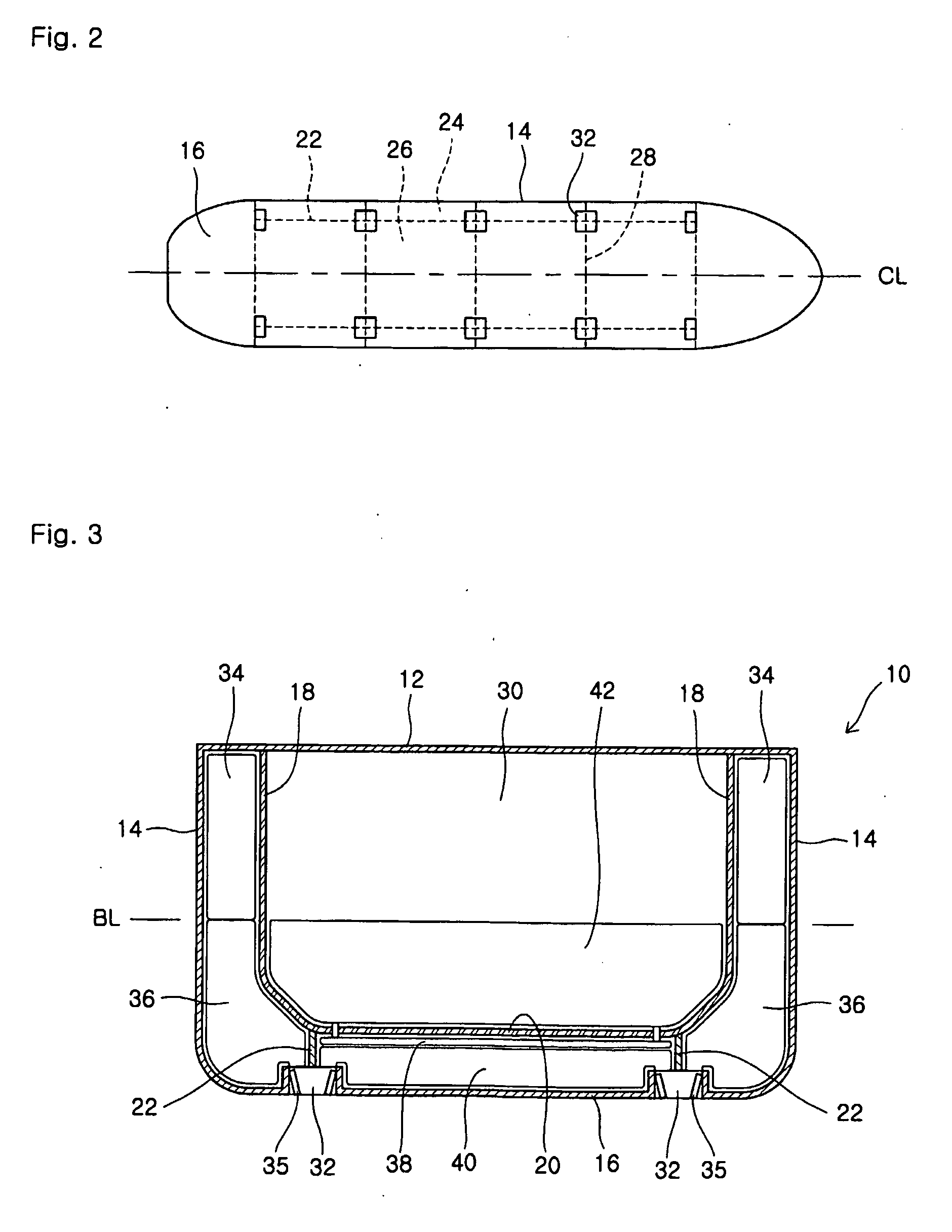
[0034]The hull structure of a vessel defines the outline or framework of the vessel and is commonly formed by installing long reinforcing members to a plate member. FIG. 1 shows an example of a hull structure of a vessel according to an embodiment of the present invention. Although reinforcing members are omitted and not shown in the figures herein, those skilled in the art will understand that a variety of reinforcing members such as a keel and a stiffener can be installed at proper positions.

[0035]Referring to FIGS. 1 and 2, a double-hulled vessel 10 of the embodiment according to the present invention includes a deck 12, an outer side shell 14, and an outer bottom shell 16. Further, the vessel 10 includes an inner side shell 18 and an inner bottom shell 20 which are placed within the outer shells 14 and 16, respectively. The vessel 10 also includes cross bulkheads 28 traversing the vessel in a lateral direction. By means of the cross bulkheads 28, an inner space defined by the in...


PUM


Abstract

A double-hulled vessel has a ballast draft line previously set at an empty state thereof. The double-hulled vessel of the present invention comprises an outer shell formed on bottom and side portions of the vessel; an inner shell formed on bottom and side portions of the vessel within the outer shell; an air tube positioned between the inner and outer shells; and a seawater tube positioned between the inner and outer shells, wherein seawater holes are formed in the outer shell to be connected to the seawater tube, the seawater tube is capable of containing seawater to substantially fill a space between the inner and outer shells extending from the bottom portion of the vessel up to the ballast draft line of the side portion of the vessel when the vessel is not loaded with cargo, and the air tube is capable of containing air to substantially fill the space between the inner and outer shells of the bottom and side portions of the vessel when the vessel is loaded with cargo.

Description

TECHNICAL FIELD[0001]The present invention relates to a vessel, and more particularly, to a vessel including a seawater ballast system, such as an oil tanker or an LNG tanker.BACKGROUND ART[0002]Generally, ballast refers to weight loaded on a vessel for the stabilization of the hull. A vessel is provided with a ballast system to minimize trim / heel phenomena and provide the vessel with stabilization such that the vessel does not overturn due to wind and wave actions. For example, a vessel such as a cargo vessel is provided with a ballast tank. The vessel arrives at a port for loading cargo in a state where the ballast tank is filled with seawater. Then, the vessel is loaded with cargo and leaves for a destination port after the seawater ballast has been discharged to the outside.[0003]Solid powder or solid materials with high specific gravity are sometimes used as ballast, but water is generally used because water can be easily obtained near the vessel. Thus, most vessels include a b...

Claims


Application Information

Patent Timeline
Patent Type & Authority Applications(United States)
IPC IPC(8): B63B43/04B63B43/06B63B13/00
CPCB63B3/20B63B13/00B63B11/04B63B43/06B63J4/002C02F2103/008B63B2013/005
Inventor KIM, YONG-KYUNG
Owner KIM YONG KYUNG
Learn More