Photovoltaic Arrays, Systems and Roofing Elements Having Parallel-Series Wiring Architectures

Inactive Publication Date: 2009-08-06
CERTAINTEED CORP
View PDF11 Cites 25 Cited by
  • Summary
  • Abstract
  • Description
  • Claims
  • Application Information

AI Technical Summary

Benefits of technology

[0014]The arrays, systems and roofing elements of the present invention can result in a number of advantages. For example, in certain aspects the present invention allows the use of groups of photovoltaic elements having different size, shape, appearance and/or output rating to achieve efficien

Problems solved by technology

First, fossil fuels have become increasingly expensive due to increasing scarcity and unrest in areas rich in petroleum deposits.
Second, there exists overwhelming concern about the effects of the combustion of fossil fuels on the environment due to factors such as air pollution (from NO

Method used


Image

  • Photovoltaic Arrays, Systems and Roofing Elements Having Parallel-Series Wiring Architectures
  • Photovoltaic Arrays, Systems and Roofing Elements Having Parallel-Series Wiring Architectures
  • Photovoltaic Arrays, Systems and Roofing Elements Having Parallel-Series Wiring Architectures

Examples


Embodiment Construction

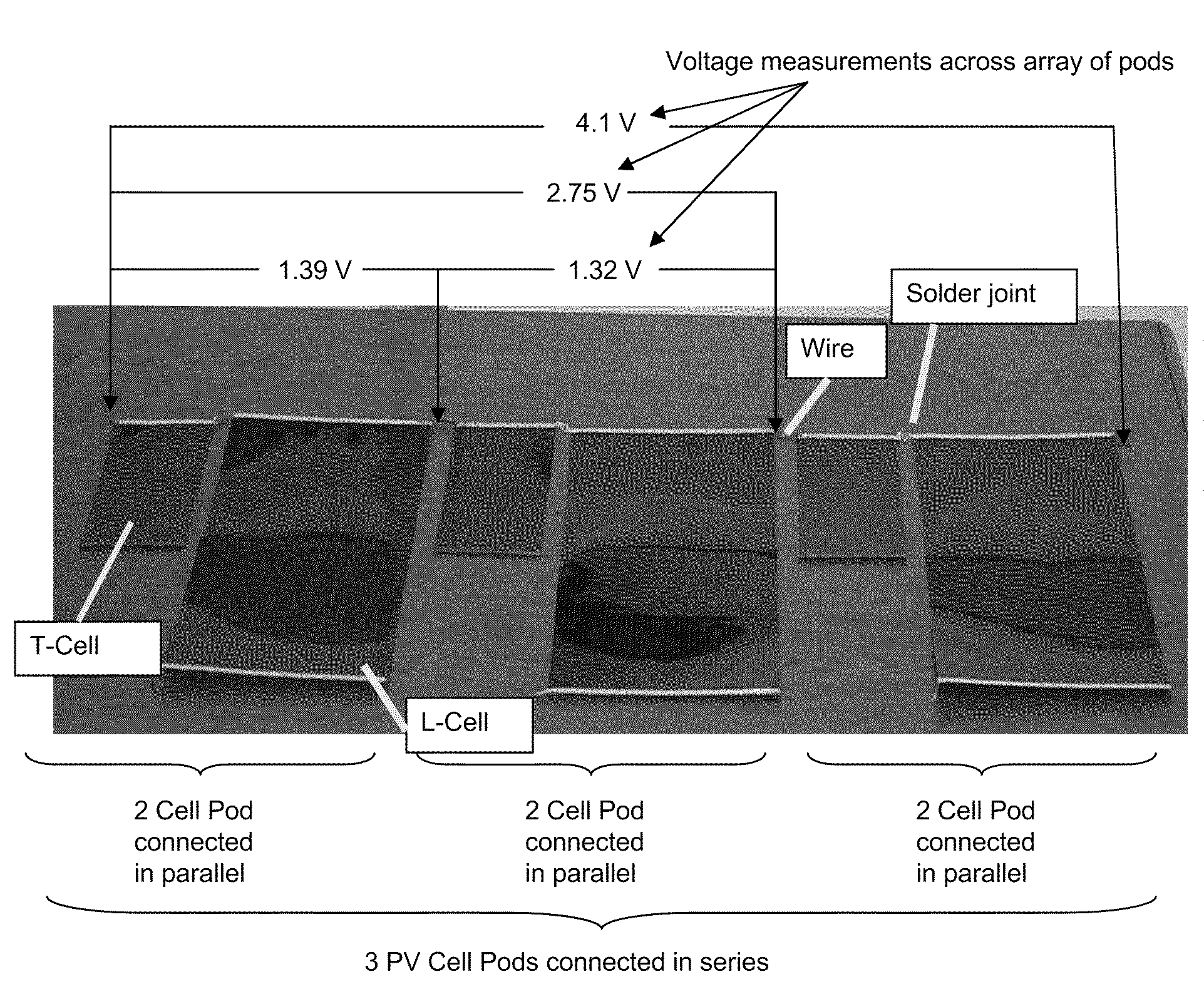
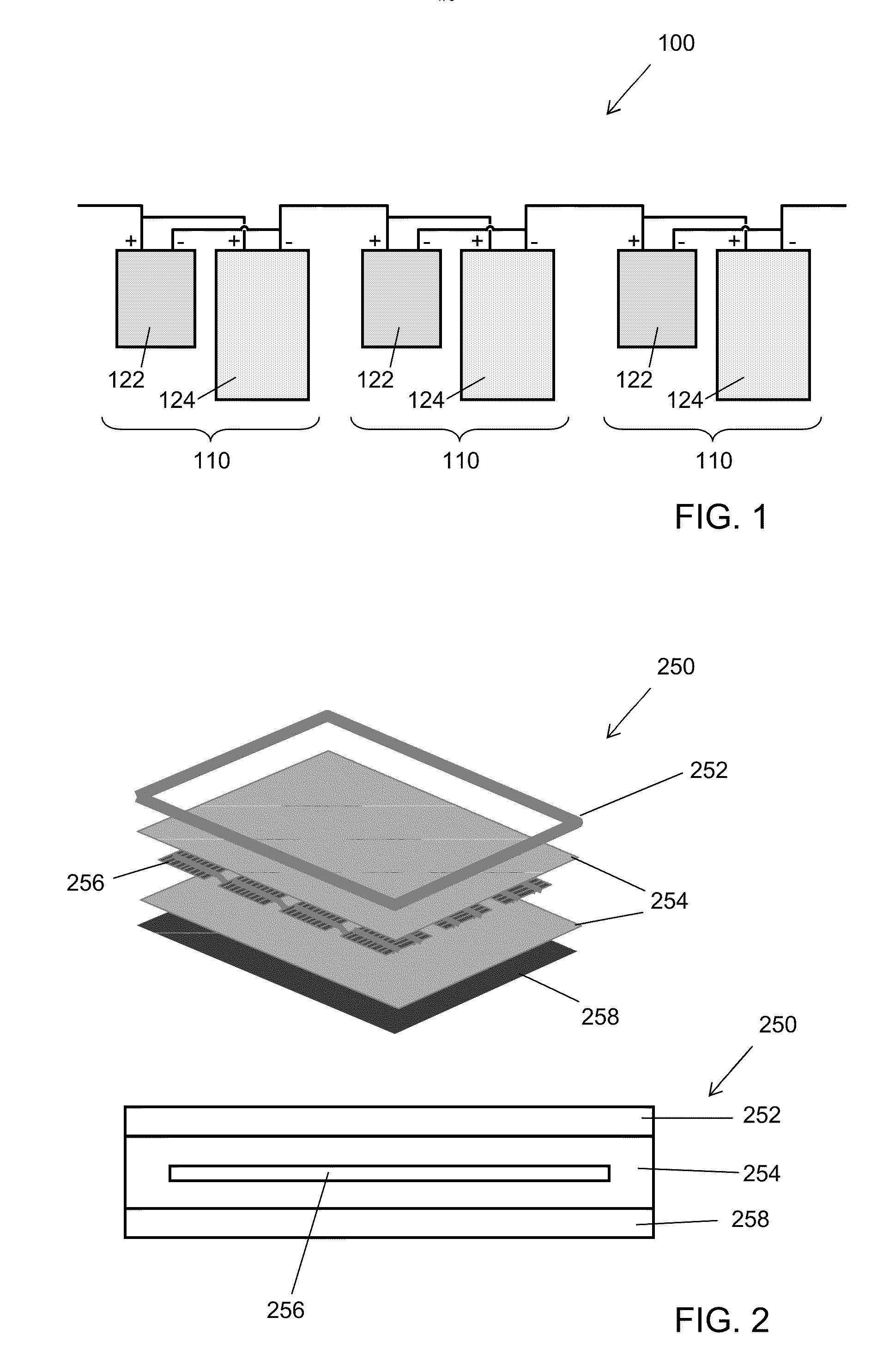
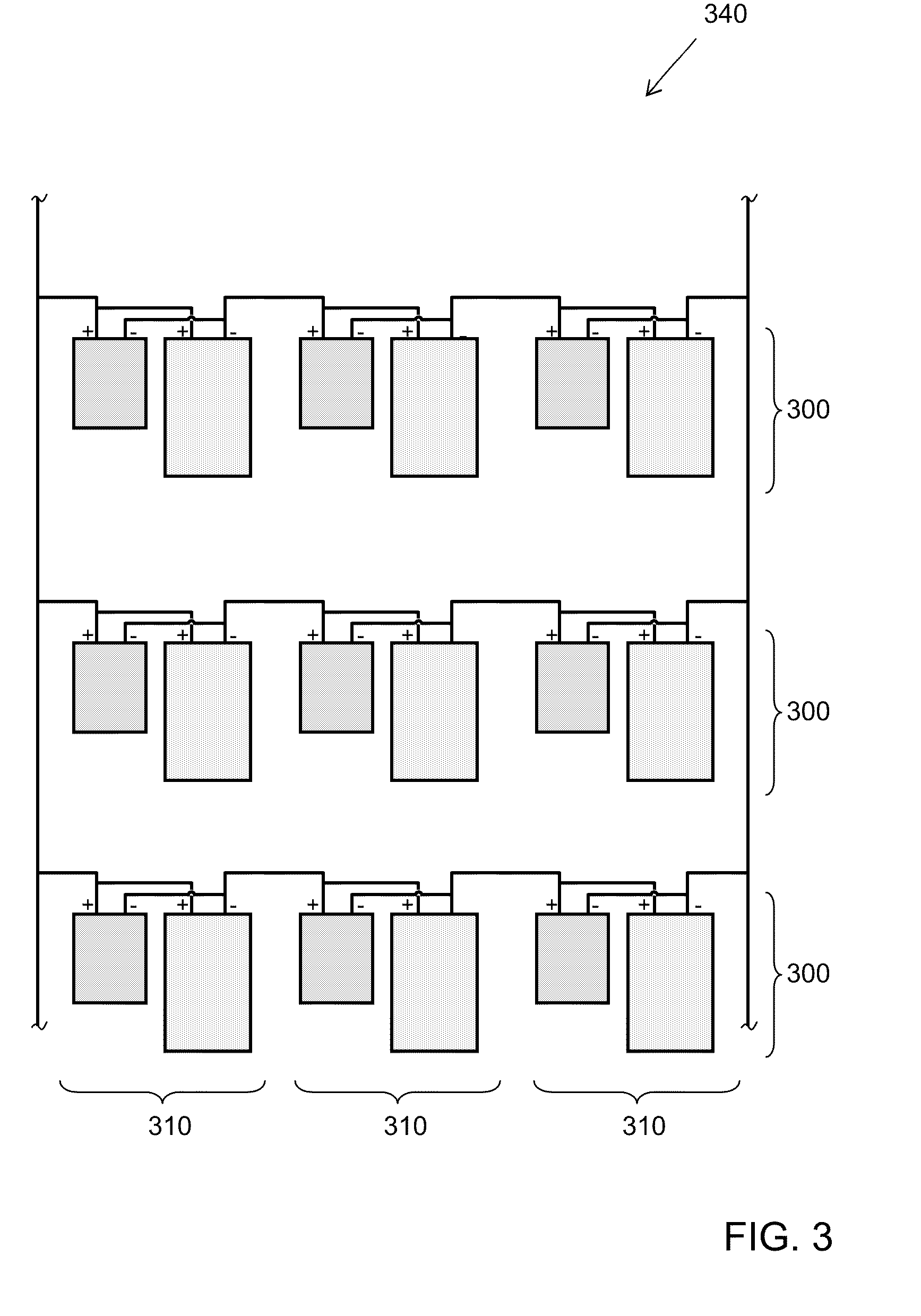
[0024]One embodiment of a photovoltaic array according to one aspect of the invention is shown in schematic view in FIG. 1. Photovoltaic array 100 comprises a plurality of pods 110 of photovoltaic elements. As used herein, a “pod” of photovoltaic elements is a grouping of a plurality of photovoltaic elements. Each pod 110 comprises a plurality of photovoltaic elements 122, 124. In each pod, the photovoltaic elements 122, 124 are electrically interconnected in parallel. The “+” and “−” symbols denote the positive and negative electrical terminals of the photovoltaic elements. Parallel interconnection within each pod allows the build-up of current, so that the output amperage of each pod approximates the sum of the individual amperages of its individual photovoltaic elements. In each pod, the photovoltaic elements have voltages within 20% of one another, and at least one photovoltaic element has an amperage at least 20% greater than the amperage of another photovoltaic element of the ...


PUM

PropertyMeasurementUnit
Fractionaaaaaaaaaa
Fractionaaaaaaaaaa
Fractionaaaaaaaaaa

Abstract

The present invention relates generally to the photovoltaic generation of electrical energy. The present invention relates more particularly to photovoltaic arrays, systems and roofing products in which a plurality of photovoltaic elements are electrically interconnected. One aspect of the present invention is a photovoltaic array including a plurality of pods of photovoltaic elements, the pods being electrically interconnected in series, each pod comprising a plurality of photovoltaic elements electrically interconnected in parallel, the photovoltaic elements of each pod having voltages within 20% of one another and at least one photovoltaic element of each pod having an amperage at least 20% greater than the amperage of another photovoltaic element of the pod.

Description

CROSS-REFERENCE TO RELATED APPLICATIONS[0001]This application claims priority under 35 U.S.C. § 119(e) to U.S. Provisional Patent Applications Ser. No. 61 / 023,610, filed Jan. 25, 2008, which is hereby incorporated herein by reference in its entirety.BACKGROUND OF THE INVENTION[0002]1. Field of the Invention[0003]The present invention relates generally to the photovoltaic generation of electrical energy. The present invention relates more particularly to photovoltaic arrays, systems and roofing products in which a plurality of photovoltaic elements are electrically interconnected.[0004]2. Technical Background[0005]The search for alternative sources of energy has been motivated by at least two factors. First, fossil fuels have become increasingly expensive due to increasing scarcity and unrest in areas rich in petroleum deposits. Second, there exists overwhelming concern about the effects of the combustion of fossil fuels on the environment due to factors such as air pollution (from N...

Claims


Application Information

Patent Timeline
IPC IPC(8): H01L31/042E04D13/18B23P15/26
CPCY02B10/12Y10T29/49355H02S20/23Y02B10/10Y02E10/50
Inventor JACOBS, GREGORY F.SHAW, WAYNE E.
Owner CERTAINTEED CORP
Why Eureka
Try Eureka