Permanent magnet elevator disk brake

a permanent magnet, elevator technology, applied in the direction of elevators, braking systems, hoisting equipment, etc., can solve the problems of increasing the attractive force generated by the electromagnet, inability to maintain the magnetic field, and inherently unstable electromagnets used for generating magnetic fields, etc., to achieve stable and durable, reduce noise

Active Publication Date: 2009-08-06
OTIS ELEVATOR CO
View PDF11 Cites 5 Cited by
  • Summary
  • Abstract
  • Description
  • Claims
  • Application Information

AI Technical Summary

Benefits of technology

[0011]Accordingly, an example brake provides for controlled movement and application of the brake such that noise can be reduced without the use of damping bodies that wear and require replacement. Further, the example brake assembly provides a stable and durable brake assembly.

Problems solved by technology

Electromagnets utilized for generating the magnetic field are inherently unstable in that attractive forces generated by the electromagnet increase as the moveable plate moves out of engagement toward a housing.
The movement of the plate though this air gap and resulting contact with the brake rotor or a housing can result in objectionable noise that can be heard within the elevator car.
Magnetic fields increase as the ferromagnetic parts come closer together, tending to create an acceleration of the movable plate on lifting that can produce objectionable noises.
If the magnetic field decays too quickly when dropping the brake, then the movable plate is accelerated by the springs against the brake rotor and brake housing also generating noise.
However, such a device can cause undesirable delays in engaging the brake, while not sufficiently reducing the noise.
Disadvantageously, the O-rings are subject to creep, stress relaxation and aging.
Over time these factors degrade the O-ring causing a noticeable increase in noise, along with a reduction in the force that engages the brake.
Such devices also suffer from the limited life span associated with the O-rings.

Method used


Image

  • Permanent magnet elevator disk brake
  • Permanent magnet elevator disk brake
  • Permanent magnet elevator disk brake

Examples


Embodiment Construction

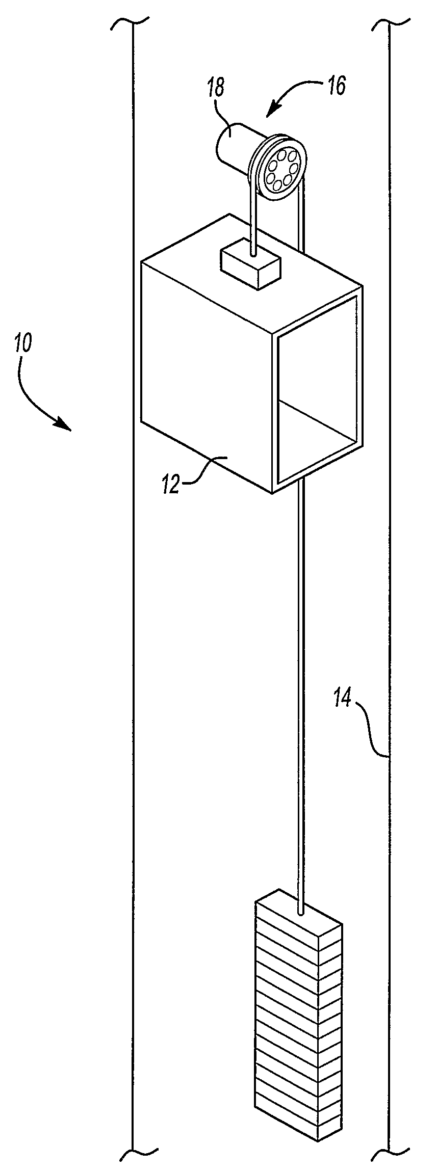
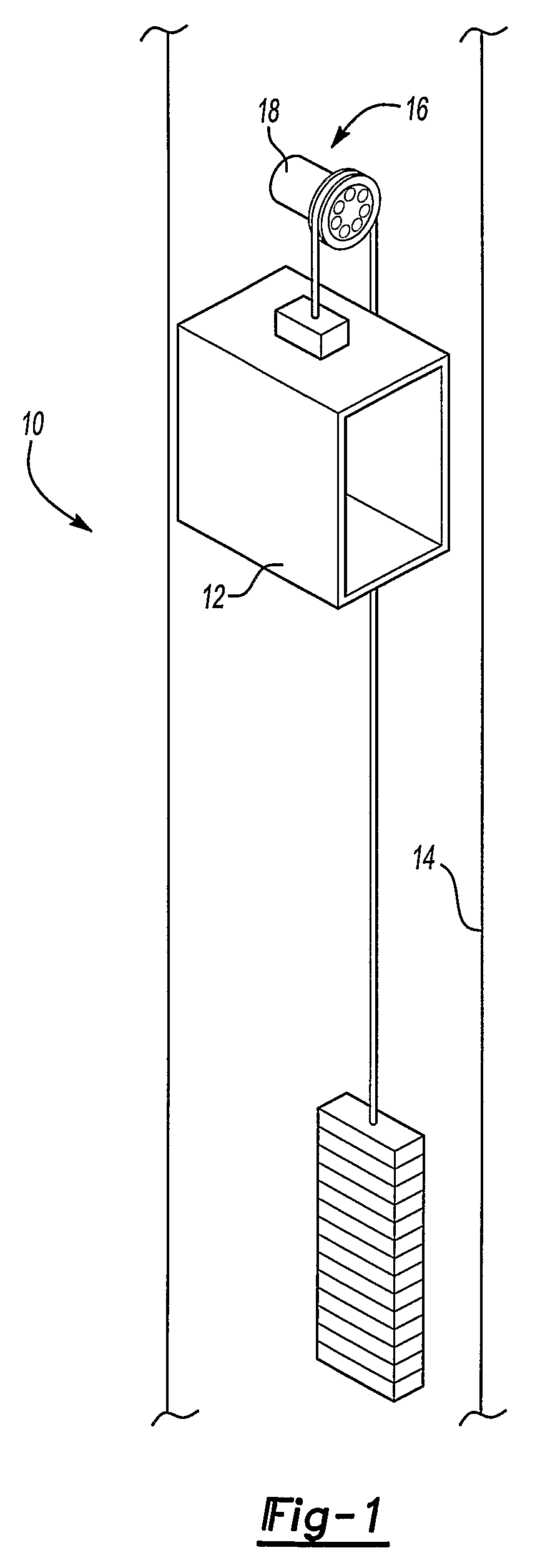
[0020]FIG. 1 schematically shows an elevator system 10 including an elevator car 12 movable within a hoistway 14. A motor 16 moves the elevator car 12 in a known manner. A brake assembly 18 utilizes a permanent magnet in combination with an electromagnet to stabilize actuation. The brake assembly 18 is mounted adjacent the motor 16 for stopping and holding the elevator car 12 at a desired position within the hoistway 14.

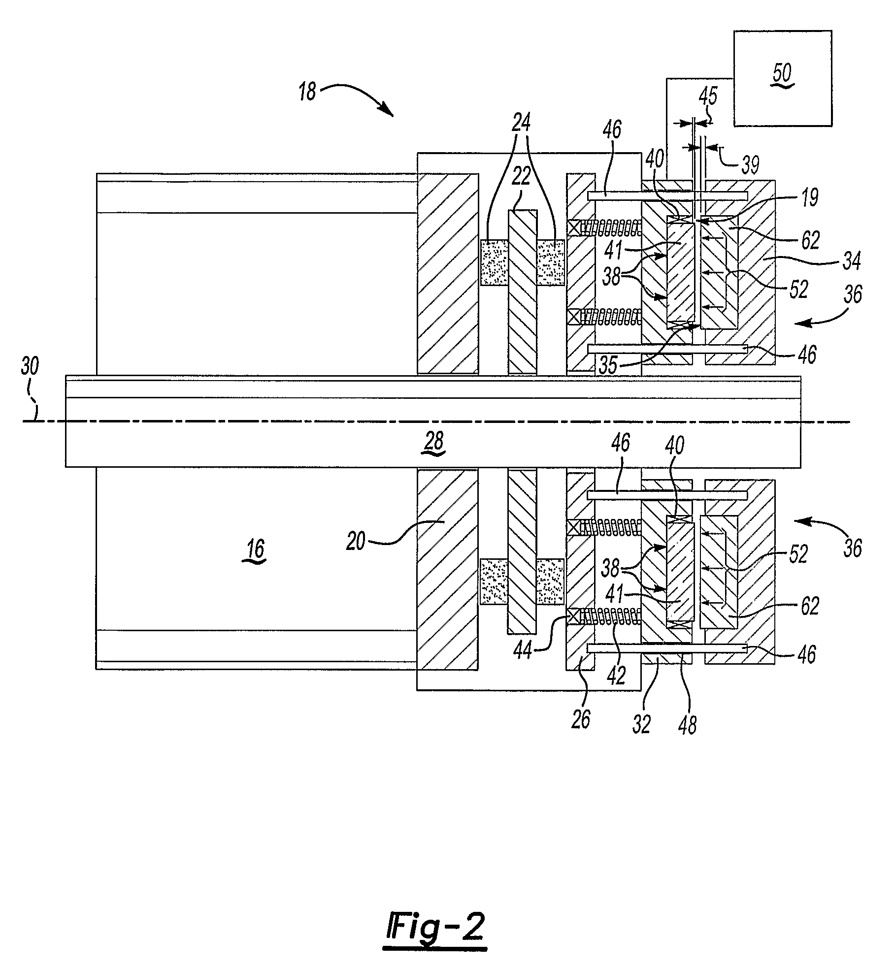
[0021]Referring to FIG. 2, an example brake assembly 18 is schematically shown in an applied or dropped position. The motor 16 drives a shaft 28 about an axis 30. The shaft 28 extends from the motor 16 and into the brake assembly 18. The brake assembly 18 includes a fixed housing 20, an axially movable disk 22 and an axially movable plate 26. The disk 22 includes friction material 24 that engages both the housing 20 and the plate 26 when in the dropped position. Further, the disk 22 is keyed to the shaft 28 in a known manner to allow axial movement but prevent rotati...


PUM


Abstract

A brake assembly (18) includes a permanent magnet (36) that generates a first magnetic field (52) in a direction that causes application of a clamping force on a brake disk (22). An electromagnet (38) is energized with current of a proper polarity to generate a second magnetic field (54) opposite the first magnetic field (52). The rate and magnitude at which current is applied produces a controlled repulsive force between the two magnetic fields (52, 54) to disengage the brake disk (22). As a distance between the permanent magnet (36) and the electromagnet (38) increases, the difference in field strength decreases until an equilibrium position is obtained. The brake is applied and released in a controlled manner by varying the strength of the second magnetic field (54) relative to the first magnetic field generated by the (36).

Description

FIELD OF THE INVENTION[0001]This invention generally relates to elevator systems. More particularly this invention relates to an elevator braking system.DESCRIPTION OF THE RELATED ART[0002]Elevator systems include a braking system to stop and hold an elevator car in a desired position. Typically, a braking system includes springs that force an axially moveable plate against a brake rotor having brake lining material. The resulting friction between the movable plate and the lining material stops and holds the elevator in place. Engagement of the moveable plate is known in the art as dropping the brake and is typically the default condition. The moveable plate is disengaged from the brake lining by a magnetic field generated by an electromagnet. The attractive force generated by the magnetic field overcomes the force of the springs and pulls the moveable plate away from the brake rotor. This is known in the art as lifting the brake.[0003]Electromagnets utilized for generating the magn...

Claims


Application Information

Patent Timeline
Patent Type & Authority Applications(United States)
IPC IPC(8): B66B9/00B60L7/00
CPCB66D5/14F16D2129/065F16D2121/22B66D5/30
Inventor FARGO, RICHARD N.
Owner OTIS ELEVATOR CO
Why Eureka
Try Eureka