Darrieus water wheel turbine

a technology of water wheel turbine and turbine blade, which is applied in the direction of motors, electrical equipment, control systems, etc., can solve the problems of increasing flow turbulence, increasing cost and complexity, and reducing energy conversion efficiency, so as to reduce system stress, increase energy output, and be easily scalable

Active Publication Date: 2009-08-06
STABINS PETER ANDREW
View PDF6 Cites 26 Cited by
  • Summary
  • Abstract
  • Description
  • Claims
  • Application Information

AI Technical Summary

Benefits of technology

[0010]It is an object of this invention to provide a simple, reliable, self-starting and low-cost Darrieus-type hydroelectric turbine system which eliminates the “counter-force effect” inherent to classical Darrieus turbine designs.
[0012]By having turbine blades rotating freely through the air when they are moving counter to the direction of water flow, the blades avoid having to move directly against the flow. The counter-force effect inherent to Darrieus type turbines is eliminated, greatly reducing stress on the system and increasing energy output. Such a turbine is also self-starting as no counter-force caused by the flow needs to be overcome.
[0013]Besides eliminating the counter-force effect, the invention is easily scalable and therefore more simple and economic than the Davis turbine. For example, to utilize the invention in a wide river the only adjustment is a longer set of blades. A single shaft, power generator and gearing system (if necessary) are required. In contrast, an equivalent Davis turbine system requires a multitude of vertical shafts, gears, generators and electrical systems, resulting in increased cost and complexity. Additional support structures are also necessary, increasing flow turbulence and decreasing energy conversion efficiency.
[0014]To further increase energy conversion efficiency the turbine can be sized to fully traverse the width and depth of the water flow channel. This arrangement forces all the water flow through the unit, permitting the Betz limit for energy conversion efficiency (59.3%) for turbines in open flow to be exceeded. Efficiencies approaching that of traditional reaction turbines are theoretically possible, without the construction of ducts, penstocks or tailraces.

Problems solved by technology

In contrast, an equivalent Davis turbine system requires a multitude of vertical shafts, gears, generators and electrical systems, resulting in increased cost and complexity.
Additional support structures are also necessary, increasing flow turbulence and decreasing energy conversion efficiency.

Method used


Image

  • Darrieus water wheel turbine
  • Darrieus water wheel turbine
  • Darrieus water wheel turbine

Examples


Embodiment Construction

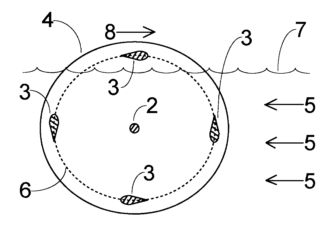
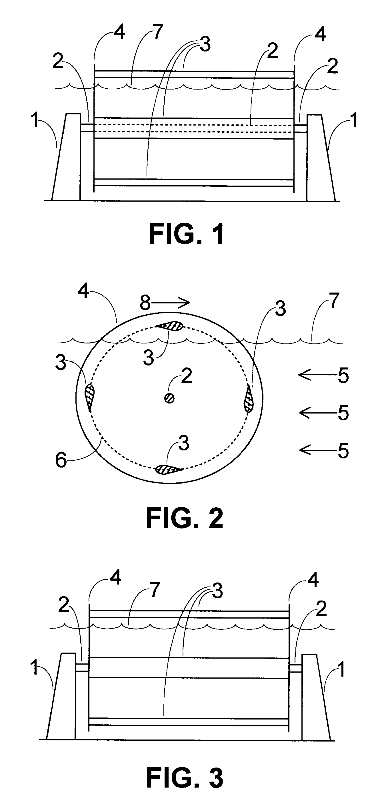
[0025]FIG. 1 is a frontal view down the direction of water flow for the best embodiment of the invention. Shaft supports 1 elevate a shaft 2 and permit its rotation. The longitudinal axis of the shaft 2 is horizontal and perpendicular to the direction of water flow. Attached to the shaft are two blade support members 4, each one being either a disc, radial spokes or any other blade support mechanism known in the art. A set of wing-like airfoil blades 3 extend between the blade support members 4. Each blade 3 has a long rectangular profile between the two blade support members 4 and a constant teardrop airfoil cross-section along its longitudinal axis, as shown in FIG. 2. A blade 3 can be constructed from a solid and non-flexible material such as metal, aluminum or reinforced polymer. The water flowing past each blade 3 creates lift and some drag, causing the blade support members 4 to rotate. The shaft 2, which passes through the centre of each blade support member 4, is thereby rot...


PUM


Abstract

A reaction turbine system for the generation of hydroelectricity is disclosed. It consists of a Darrieus type turbine with a horizontal axis of rotation. The blades may be straight or helical, and are held equidistant from the central rotating shaft by blade support members. The blades are oriented so that a blade at its rotational apex moves directly opposite to the direction of water flow. The turbine is elevated such that the top portion, where blades travel directly against the direction of water flow, is in the air and above the water level. This design greatly reduces stresses on the system and increases energy output relative to a Darrieus turbine fully immersed in water flow. This design also enables the turbine to self-start.

Description

TECHNICAL FIELD[0001]This invention relates to reaction turbines for the generation of hydroelectricity.BACKGROUND ART[0002]Devices which take advantage of the energy in falling water have existed for several centuries. The earliest example is the water wheel. It is an impulse device which uses a multitude of buckets or paddles to catch falling or moving water, depositing it at a downstream point. The movement of the buckets or paddles spins a central supporting shaft which can do work or be used to generate power.[0003]In the late 1800's and early 1900's hydro power innovators discovered the advantages of reaction turbines, which mainly generate power from pressure and energy differences in stream flow. These turbines extract more power from streams than water wheels, rotate at higher speeds and accept much larger water flow volumes. Reaction turbines, such as the Francis or Kaplan, are therefore almost exclusively used at high flow hydroelectric sites. Both of these designs utiliz...

Claims


Application Information

Patent Timeline
Patent Type & Authority Applications(United States)
IPC IPC(8): F03B13/10
CPCF03B3/12Y02E10/223F05B2240/242F05B2240/212Y02E10/20
Inventor STABINS, PETER ANDREW
Owner STABINS PETER ANDREW
Why Eureka
Try Eureka