Screen for motorcycle

Active Publication Date: 2009-08-06
HONDA MOTOR CO LTD
View PDF11 Cites 24 Cited by
  • Summary
  • Abstract
  • Description
  • Claims
  • Application Information

AI Technical Summary

Benefits of technology

[0005]It is an object of an embodiment of the present invention to provide a screen for a motorcycle which al

Problems solved by technology

Although the air flow from between the cowling and the wind screen flows along the surface of the cowling, the probability occurs that the air flow may not sufficiently flow to the rear face of the wind screen.
If the air flow does not sufficiently flow to t

Method used


Image

  • Screen for motorcycle
  • Screen for motorcycle
  • Screen for motorcycle

Examples


first embodiment

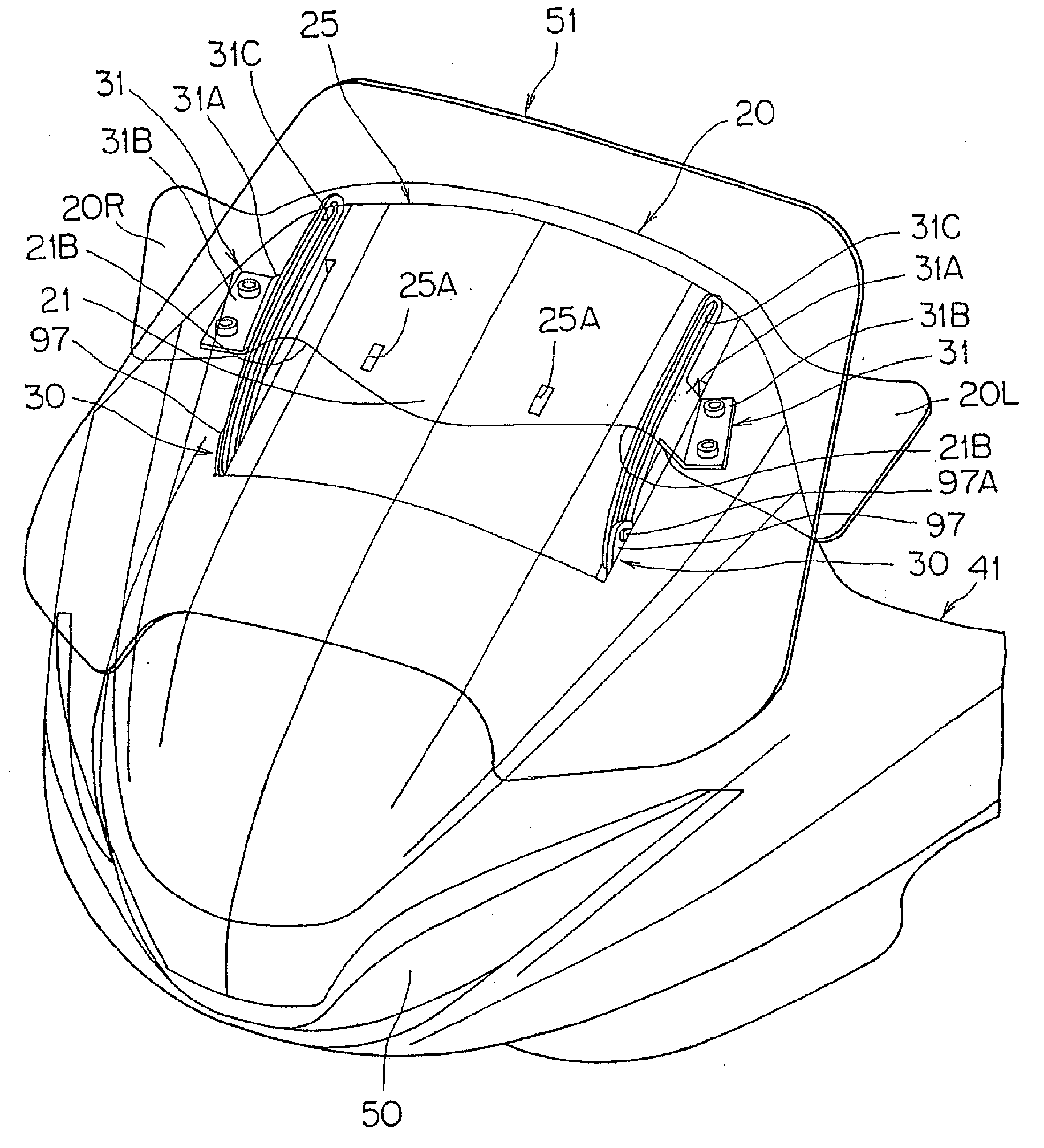
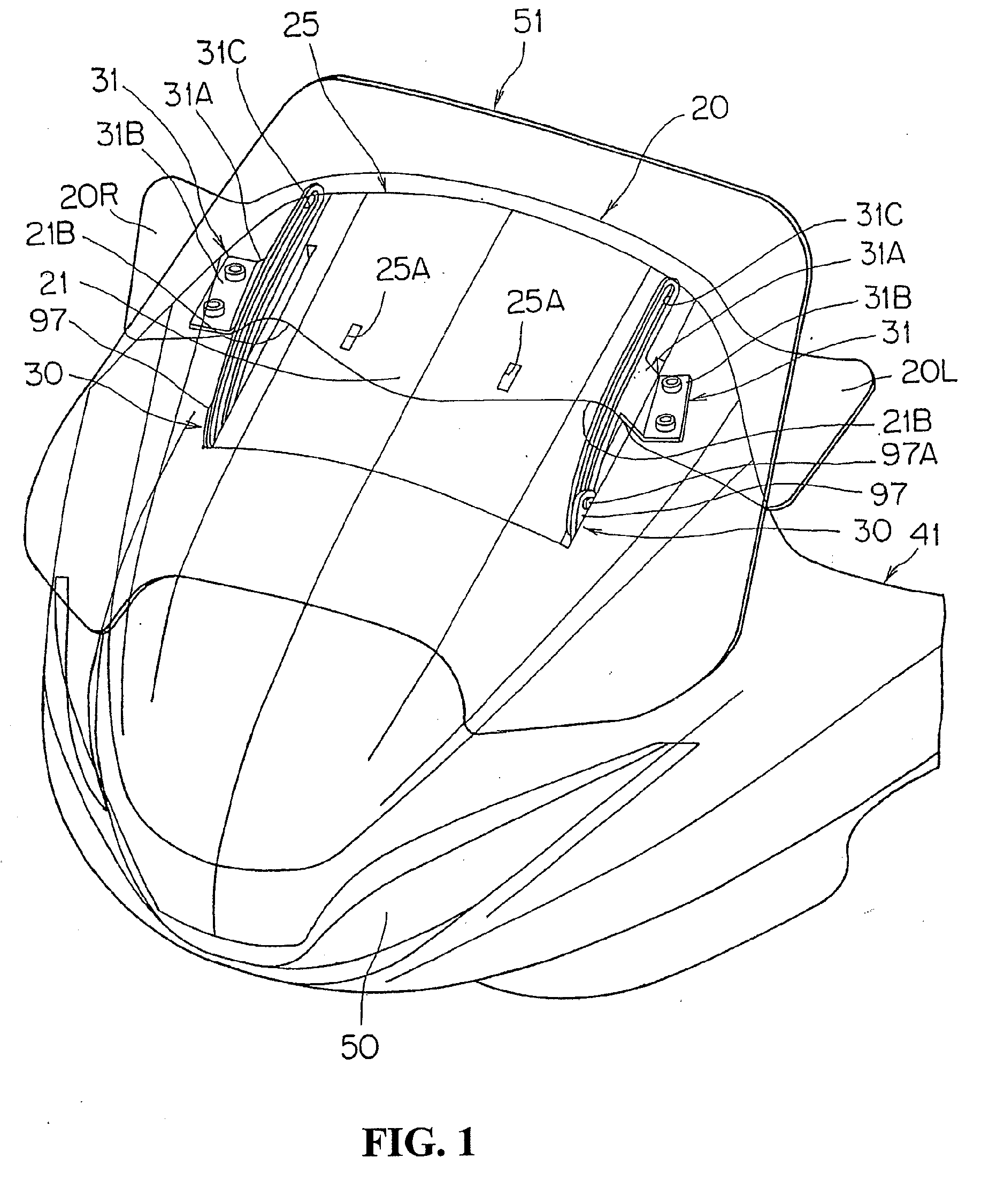
[0033]FIG. 1 is a perspective view showing a front portion of a motorcycle according to the present invention.

[0034]The motorcycle includes an upper cowling 41 which covers a front upper portion of a vehicle body, and a headlamp 50 disposed at a front portion of the upper cowling 41. A wind screen 51 is formed from a transparent resin material and is disposed at a front upper portion of the upper cowling 41.

[0035]The upper cowling 41 is formed in a streamlined shape wherein it expands smoothly in a vehicle widthwise direction and an upward and downward direction toward the rear direction of the vehicle body such that air flow from forwardly of the vehicle body is rectified and flows around the driver without directly coming to the driver, and the wind screen 51 is formed in a substantially to be trapezoidal shape wherein the width thereof decreases toward the upward direction. This wind screen 51 is formed as a movable wind screen whose height and inclination angle can be adjusted b...

second embodiment

[0070]FIGS. 7 to 10 show a screen for a motorcycle according to a

[0071]In the second embodiment, the connection mechanism 30 which connects the sub screen 20 to the wind screen 51 includes a pair of left and right sub screen holders (hereinafter referred to as holders) 150 provided on the wind screen 51 side, and the sub screen 20 is connected to the wind screen 51 through the holders 150 as seen in FIG. 7.

[0072]More particularly, a pair of left and right movable element fixing side stays 97 are attached to the wind screen 51 as shown in FIG. 7. Boss portions 97B which project from the inner side faces are provided individually on the movable element fixing side stays 97, and the holders 150 are fitted on the boss portions 97B and screws 151 are tightened. In this instance, the holders 150 are supported for pivotal motion (for tilting motion) around the boss portions 97B respectively.

[0073]Support plates 153 of a substantially L-shaped section are secured to the pair of left and rig...

third embodiment

[0083]FIGS. 11 to 13 show a screen of a motorcycle according to a Here, FIG. 11 is an exploded perspective view showing the screen together with peripheral elements, FIG. 12 is a side sectional view of the screen, and FIG. 13 is a sectional view taken along line XIII-XIII of FIG. 12.

[0084]In the third embodiment, as shown in FIGS. 1I and 12, a pair of left and right guide arms 181, 181 extending along the forward and backward direction below the sub screen 20 are provided, and a mechanism for varying the inclination angle of the sub screen 20 in response to movement of the wind screen 51, that is, the connection mechanism 30 for connecting the sub screen 20 to the wind screen 51, is formed from the guide arms 181, 181.

[0085]More particularly, the pair of left and right guide arms 181, 181 are formed from plate-formed members of a substantially L-shaped sectional shape wherein vertical plate portions 181A, 181A mounted at end portions thereof for pivotal motion on side faces of the ...


PUM


Abstract

A screen for a vehicle which allows air flow to flow appropriately along a rear face of a wind screen having an adjustable inclination angle. A baffle plate inclined toward the rear direction of a vehicle body is provided between a cowling which covers a front upper portion of the vehicle body and a movable wind screen. The inclination angle of the baffle plate can be adjusted so that air flow from between the cowling and the movable wind screen flows along a rear face of the movable wind screen.

Description

CROSS-REFERENCE TO RELATED APPLICATIONS[0001]The present application claims priority under 35 USC 119 to Japanese Patent Application No. 2008-024746 filed on Feb. 5, 2008 and Japanese Patent Application No. 2008-236185 filed on Sep. 16, 2008 the entire contents of which are hereby incorporated by reference.FIELD OF THE INVENTION[0002]A screen for a motorcycle which includes a wind screen having an adjustable inclination angle.DESCRIPTION OF BACKGROUND ART[0003]Motorcycle are known that include a movable wind screen having an adjustable height on a cowling which covers a front upper portion of a vehicle body. Some movable wind screens of this type have an inclination angle which is adjusted in an interlocked relationship with adjustment of the height. See, for example, Japanese Patent Laid-Open No. 2003-81160.[0004]However, in the conventional configuration, if the wind screen is configured for adjustment to a higher position, at a higher position of the wind screen, the wind screen ...

Claims


Application Information

Patent Timeline
IPC IPC(8): B62J17/02B62J17/04
CPCB62J17/04
Inventor TSUDA, HARUKAOKUBO, TAKEFUMI
Owner HONDA MOTOR CO LTD
Why Eureka
Try Eureka