Switched-capacitor circuit having switch-less feedback path

a switch-less, capacitor-based technology, applied in the direction of switching capacitors, amplifiers with semiconductor devices only, amplifiers with semiconductor devices, etc., can solve the problems of non-ideal switches, non-zero resistance between the first and second terminals, and invariably implementing non-ideal switches. , to achieve the effect of reducing the resistance between the first and second terminals, and reducing the resistan

Active Publication Date: 2009-08-06
ANALOG DEVICES INC
View PDF4 Cites 11 Cited by
  • Summary
  • Abstract
  • Description
  • Claims
  • Application Information

AI Technical Summary

Problems solved by technology

One problem, however, with the transistor implementation 22 of FIG. 2, and with other transistor implementations of the switch 20, is that they typically implement non-ideal switches.
However, the transistor implementation 22 of FIG. 2, and also other transistor implementations, typically presents, among other non-ideal characteristics, a non-zero resistance between the first and second terminals when enabled.
Non-ideal switches can in turn impact the performance of switched-capacitor circuits containing such switches.
A switched-capacitor circuit, which includes the transistor switch embodiment 22 of FIG. 2, or other non-ideal switch embodiments, in a signal path, may suffer from adverse effects of the non-zero impedance in the enabled state.
For example, this non-zero impedance may adversely affect a frequency response of the switched-capacitor circuit.

Method used


Image

  • Switched-capacitor circuit having switch-less feedback path
  • Switched-capacitor circuit having switch-less feedback path
  • Switched-capacitor circuit having switch-less feedback path

Examples


Embodiment Construction

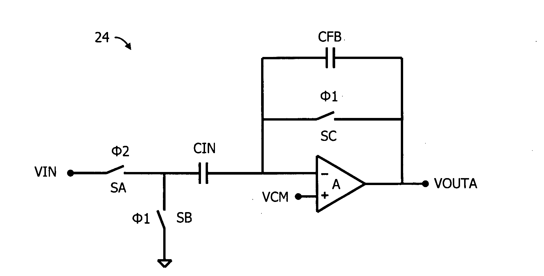
[0038]FIG. 3 depicts an embodiment of a first switched-capacitor circuit 24 that can be used to implement a gain stage, among other potential functionalities. The first switched-capacitor circuit 24 includes first and second input switches SA, SB, an input capacitor CIN, a feedback capacitor CFB, a feedback switch SC, and an amplifier A having differential input terminals and a single output terminal. The input capacitor CIN is connected between the first and second input switches SA, SB and an inverting input terminal of the amplifier A. The feedback capacitor CFB and feedback switch SC are connected between the output terminal of the amplifier A, which is also connected to an output node (having an output voltage VOUTA) of the first switched-capacitor circuit 24, and the inverting input terminal. The first and second input switches SA, SB are connected between the inverting input of the amplifier A and an input node of the switched-capacitor circuit 24 configured to receive an inp...


PUM


Abstract

A switched-capacitor circuit includes a plurality of cascaded differential-input, single-ended-output amplifiers. A negative feedback path, from an output terminal of a last of the cascaded amplifiers to an input terminal of a first of the cascaded amplifiers, is configured to exclude, and not be shorted out by, any switches.

Description

CROSS-REFERENCE TO RELATED APPLICATIONS[0001]This application claims priority to U.S. Provisional Patent Application No. 61 / 063,220, to Iliana Fujimori Chen and Christopher W. Mangelsdorf, filed on Feb. 1, 2008, entitled “Switched-Capacitor Circuit with Switch-less Feedback Path,” which is herein incorporated by reference in its entirety.BACKGROUND INFORMATION[0002]Switched-capacitor circuits typically include switches, along with amplifiers, in arrangements configured to implement specific input-to-output transfer functions. For example, switched-capacitor circuits can be used to implement gain stages, filters, D / A converters, and many other types of circuits. The switches of switched-capacitor circuits are selectively switched on and off by clock signals to realize the transfer functions.[0003]FIG. 1 depicts an exemplary switch 20 that could be used in a switched-capacitor circuit. The switch 20 includes a first terminal associated with a first voltage V1, a second terminal associ...

Claims


Application Information

Patent Timeline
Patent Type & Authority Applications(United States)
IPC IPC(8): H03F1/02
CPCH03F3/005H03F3/45179H03F2203/45526H03F2203/45521H03F3/45475
Inventor CHEN, ILIANA FUJIMORIMANGELSDORF, CHRISTOPHER W.
Owner ANALOG DEVICES INC
Why Eureka
Try Eureka