Input apparatus and imaging apparatus

a technology of input apparatus and imaging apparatus, which is applied in the field of input apparatus, can solve the problems of unintended or inadvertent input operation, large consumption of conventional input apparatus, and inconvenient remote controller operation, and achieve the effect of preventing input errors and more accurate inpu

Active Publication Date: 2009-08-06
DENSO CORP
View PDF14 Cites 53 Cited by
  • Summary
  • Abstract
  • Description
  • Claims
  • Application Information

AI Technical Summary

Benefits of technology

[0023]A first object of the present invention is to provide an input apparatus capable of preventing an input error and ensuring more accurate input.

Problems solved by technology

The remote controller may be inconvenient in such points that a user gropes for the remote controller, holds it in his or her hand, and presses buttons.
The prompter-based remote controlling apparatus may cause an unintended or inadvertent input operation such as an input error due to variations in touch inputs by an operator.
However, the conventional input apparatus consumes much electric current because a video camera is always powered or a touch panel is always ready for operations.
In such case, the user may extend his or her hand to the operation panel for touch operation but may inadvertently touch the press operation section to cause an operational error.
The operation concerns the same direction and is more likely to cause an operational error than the case of placing the other operation sections.
This may degrade the accuracy of image analysis for recognizing an operation content.

Method used


Image

  • Input apparatus and imaging apparatus
  • Input apparatus and imaging apparatus
  • Input apparatus and imaging apparatus

Examples


first embodiment

[0092]The first embodiment of the present invention will be described.

first example

[0093]a) The following describes a configuration of a car navigation system that uses the input apparatus according to the example.

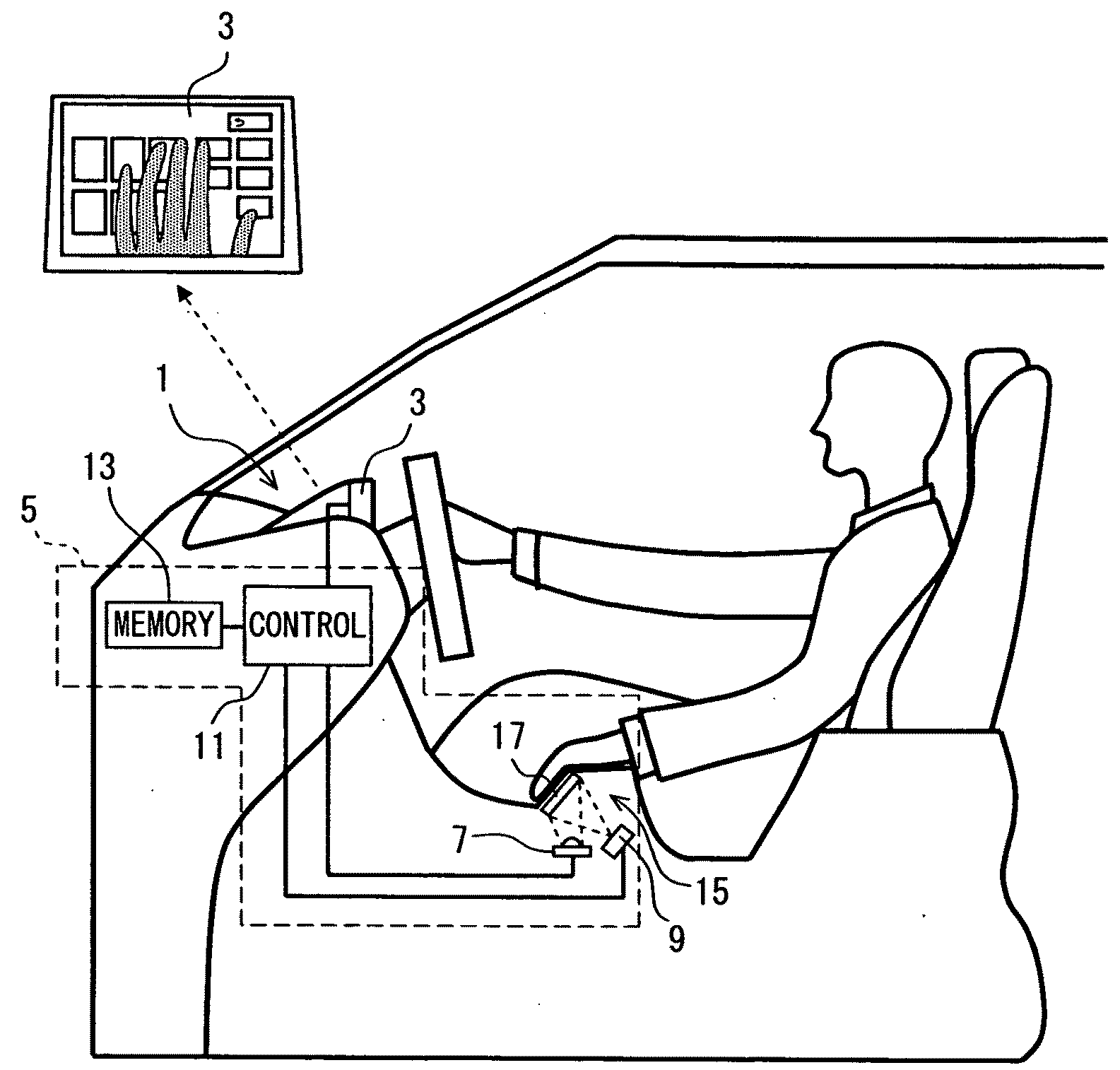
[0094]As shown in FIG. 1, a car navigation system 1 is installed in a vehicle compartment and includes a display apparatus 3 and an input apparatus 5.

[0095]The display apparatus 3 displays navigation information on a map and displays a menu image or a menu screen for manual input. The display apparatus 3 uses a liquid crystal panel and is installed in the vehicle compartment at a front position viewable from a driver.

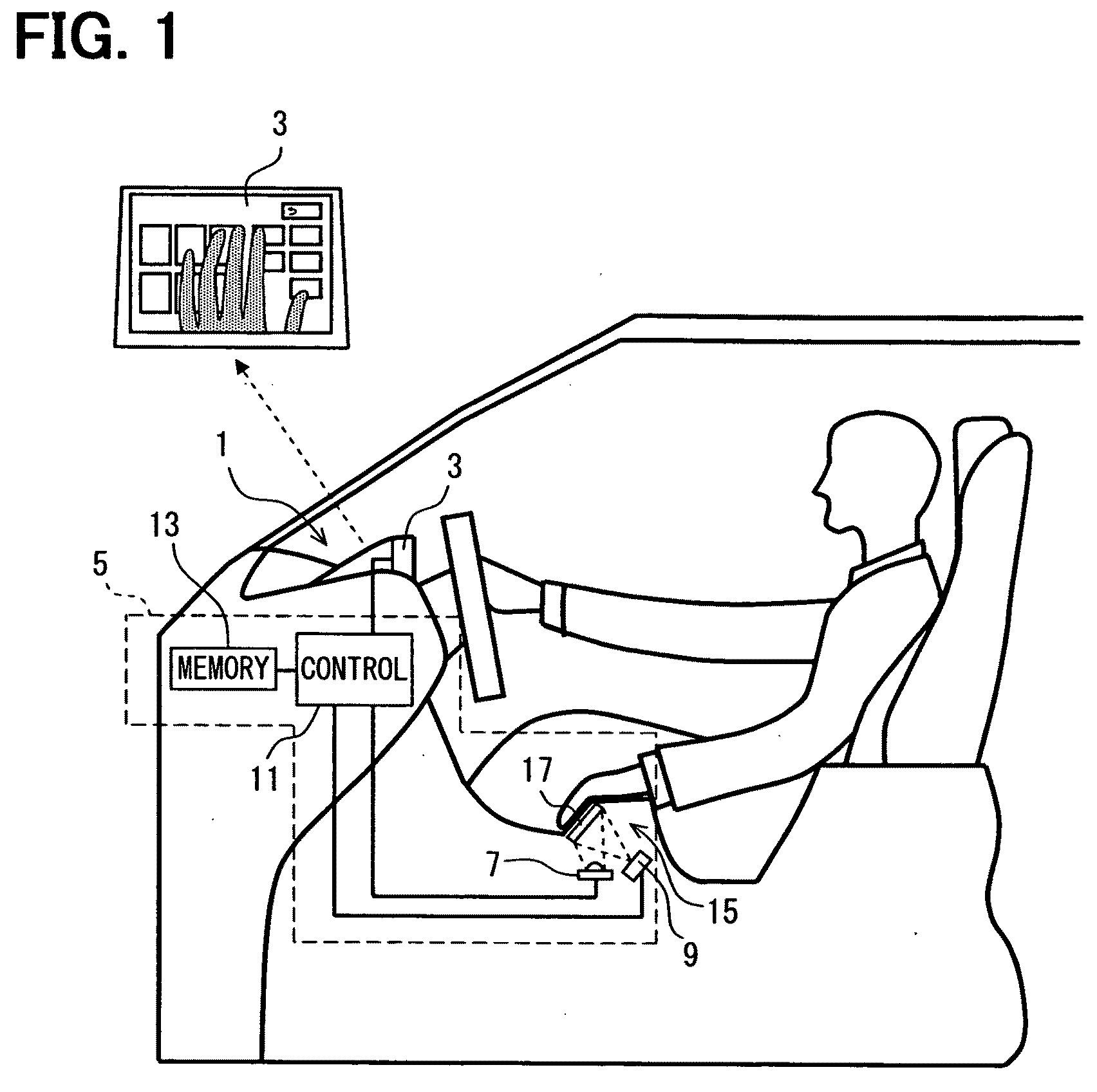
[0096]The input apparatus 5 performs processes corresponding to manual actions of the driver who operates the car navigation system 1. The input apparatus 5 includes a lighting section 7, an imaging section 9, a control section 11, an image memory 13, and an input section 15. The lighting section 7 radiates light. The imaging section 9 captures a hand and fingers. The control section 11 provides various controls. The image memory 13 stores c...

second example

[0145]The following describes the second example. The same description as the first example will be omitted for simplicity.

[0146]As shown in FIG. 7A, an input apparatus according to the example includes a touch panel 31 and an input section 35 having a palm rest 33 similarly to the first example.

[0147]In the example, the palm rest 33 is horizontal. There is an intermediate section 37 between the palm rest 33 and the touch panel 31. The top surface of the intermediate section 37 is smoothly curved.

[0148]The second example also provides the same effect as the first example.

[0149]The top surface of the intermediate section 37 may form an obtuse angle or may be multifaceted.

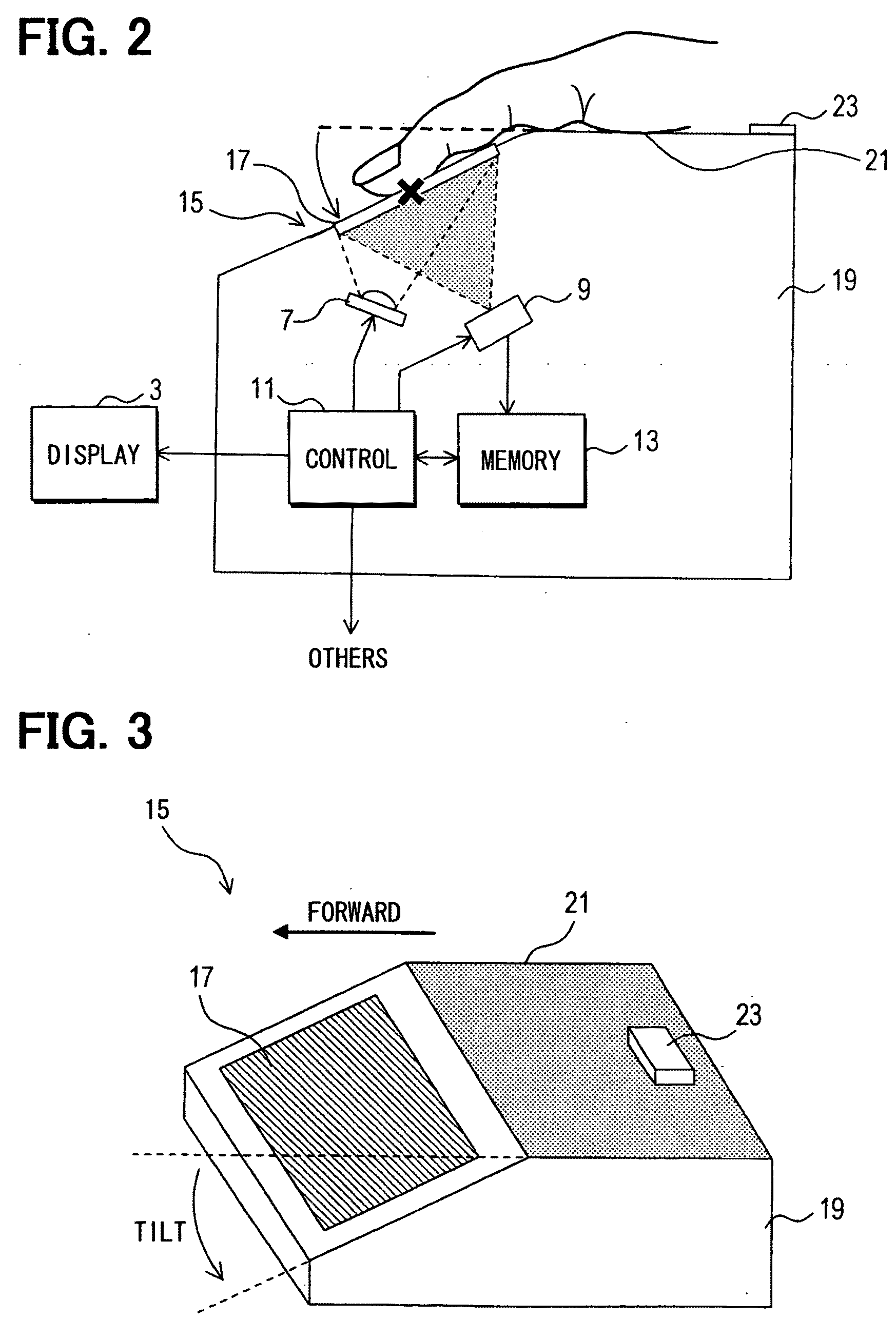
[0150]As shown in FIG. 7B, a tilt angle is formed between the touch panel 31 and the flat surface of the palm rest 33. The tilt angle is selectable in the range between 10 and 90 degrees. The tilt angle is also applicable to the other examples.


PUM


Abstract

An input section includes a palm rest and a hand detection sensor on the top surface of a housing. The input section also includes, for example, an analog resistive touch panel above the housing to the front. A palm rest is used as a base for placing a palm for manipulating the touch panel and has a flat surface slightly forward with reference to a horizontal level. The touch panel tilts below the surface of the palm rest. The touch panel is given a tilt angle so that the fingertip or the finger cushion naturally touches the surface (panel surface) of the touch panel when the palm is placed on the palm rest.

Description

CROSS REFERENCE TO RELATED APPLICATION[0001]This application is based on and incorporates herein by reference Japanese Patent Application No. 2008-20955 filed on Jan. 31, 2008, No. 2008-92919 filed on Mar. 31, 2008, No. 2008-202145 filed on Aug. 5, 2008, and No. 2008-226327 filed on Sep. 3, 2008.FIELD OF THE INVENTION[0002]The present invention relates to an input apparatus capable of manual input using a touch panel and a related imaging apparatus, for example.BACKGROUND OF THE INVENTION[0003]Patent Document 1: JP-2007-156950A[0004]Patent Document 2: JP-2007-272596A (US2007 / 0230929)[0005]Patent Document 3: JP-2000-6687A[0006]Patent Document 4: JP-2007-198574A[0007]Patent Document 5: JP-2000-106069A[0008]Patent Document 6: JP-2003-346162A[0009]A remote controller has been long known as an apparatus for operating onboard apparatuses such as a car navigation system. The remote controller may be inconvenient in such points that a user gropes for the remote controller, holds it in his o...

Claims


Application Information

Patent Timeline
Patent Type & Authority Applications(United States)
IPC IPC(8): H04N5/225G06F3/041G09G5/00
CPCG06F3/03547H04N5/2256G06F3/04886G06F3/0425H04N23/56G06F3/0488G06F3/042G06F3/0354H04N23/00
Inventor NAGATA, TAKASHIWAKIYAMA, KENICHINAKANISHI, KAZUNOBUHISATSUGU, SHINSUKE
Owner DENSO CORP
Why Eureka
Try Eureka