Power IC with an over-current protection circuit and method thereof

a protection circuit and power ic technology, applied in the direction of electric variable regulation, process and machine control, instruments, etc., can solve the problems of large power loss on too large voltage over the sensing resistor rb>1/b>, and limited output current, so as to reduce power loss and heat loss

Active Publication Date: 2009-08-06
HOLTEK SEMICON
View PDF3 Cites 25 Cited by
  • Summary
  • Abstract
  • Description
  • Claims
  • Application Information

AI Technical Summary

Benefits of technology

[0012]One particular aspect of the present invention is to have a two-stage current limit mechanism, including the constant current limit and the fold-back current limit, in the over-current protection circuit. Thereby, the output current of a power IC with the over-current protection circuit is clamped to a specified value to prevent the over-current from being occurred and decrease the power loss and heat loss generated by the power transistor when the output terminal is short-circuit. Therefore, the circuit in the power IC and the load connected with the output terminal are protected.

Problems solved by technology

Therefore, when the output current surpasses the specified value, the output current is limited.
First, because the output current flows through the sensing resistor R1, the voltage over the sensing resistor R1 is too large when the output current is large, and a great amount power is lost on the sensing resistor R1.
When the output terminal is short-circuit, a great amount of heat loss occurs.
In addition to wasting power, the power transistor M1 may be damaged when the voltage difference between the input voltage and the output voltage is large.

Method used


Image

  • Power IC with an over-current protection circuit and method thereof
  • Power IC with an over-current protection circuit and method thereof
  • Power IC with an over-current protection circuit and method thereof

Examples


Embodiment Construction

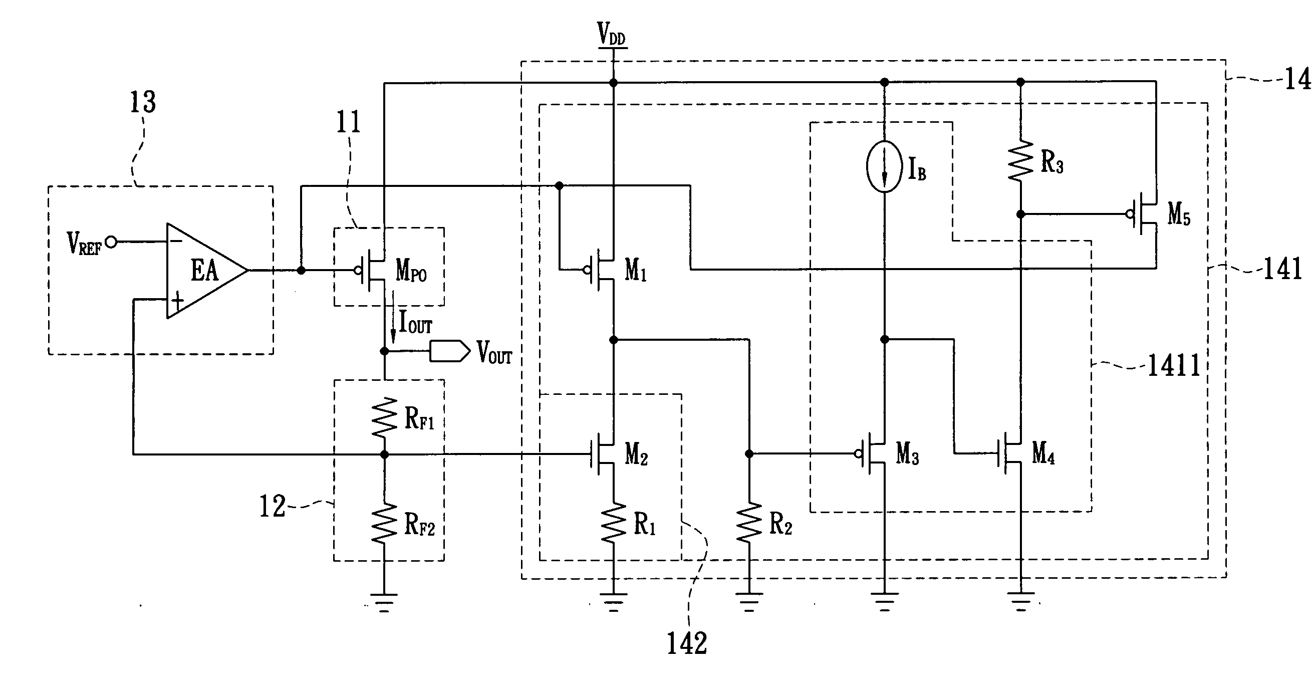
[0026]The present invention has a two-stage current limit mechanism, including the constant current limit and the fold-back current limit, in the over-current protection circuit. Thereby, a power IC with the over-current protection circuit will not generate the over-current symptom and decrease the power loss and heat loss generated by the power transistor when the output terminal is short-circuit. Therefore, the circuit in the power IC and the load connected with the output terminal are protected.

[0027]Reference is made to FIG. 3, which shows a block diagram of the power IC with an over-current protection of an embodiment of the present invention. In this embodiment, a power IC 1 is provided for receiving an input voltage VDD generated from an input voltage source 2 and converting the input voltage VDD into an output voltage VOUT for load 3 in a normal operation status. The power IC 1 includes a power transistor 11, a feedback circuit 12, an output control unit 13, and an over-curr...


PUM


Abstract

A power IC with an over-current protection receives an input voltage and converts the input voltage into an output voltage to a load. The present invention controls a power transistor to provide an output current to the load, and uses the output control unit to control the power transistor. Furthermore, the over-current protection circuit has a constant current limit threshold and a fold-back current limit threshold for controlling the power transistor. When the output current is larger than the constant current limit threshold, the output current is clamped to a constant current value to descend the output voltage to a rated value. When the output current is larger than the fold-back current limit threshold, the output current is limited to a low current value to descend the output voltage to zero. Thereby, the inner circuit of the power IC and the load are protected.

Description

BACKGROUND OF THE INVENTION[0001]1. Field of the Invention[0002]The present invention relates to a power IC and an over-current protection circuit and method thereof. In particular, this invention relates to a power IC and an over-current protection circuit and method thereof that has a two-stage current limit protection mechanism.[0003]2. Description of the Related Art[0004]As technology develops, a variety of advanced electronic devices are produced. In addition to enhancing functionality of the circuits of the electronic devices, a great amount of efforts are exerted to the power circuit—the power IC, such as voltage regulators, that will affect the stability of the electronic devices.[0005]The voltage regulator is a circuit that provides a constant voltage to the load. The output current of the voltage regulator is adjusted according to the resistance of the load so that the output voltage is maintained at a constant voltage. The characteristic of the voltage regulator depends o...

Claims


Application Information

Patent Timeline
Patent Type & Authority Applications(United States)
IPC IPC(8): H02H3/08
CPCG05F1/573
Inventor CHEN, CHIA-MINJIAN, MING-HONG
Owner HOLTEK SEMICON
Why Eureka
Try Eureka