Fiber Optic Acceleration and Displacement Sensors

a technology of fiber optics and sensors, applied in the field of fiber optic sensors for displacement and acceleration, can solve the problems of difficult remote control and multiplexing of these sensors, large sensor systems, and high cos

Active Publication Date: 2009-08-06
THE UNITED STATES OF AMERICA AS REPRESENTED BY THE SECRETARY OF THE NAVY +1
View PDF17 Cites 22 Cited by
  • Summary
  • Abstract
  • Description
  • Claims
  • Application Information

AI Technical Summary

Problems solved by technology

Such sensor systems can be bulky, expensive, and subject to electromagnetic interference.
Remote control and multiplexing of these sensors can also be difficult.

Method used


Image

  • Fiber Optic Acceleration and Displacement Sensors
  • Fiber Optic Acceleration and Displacement Sensors
  • Fiber Optic Acceleration and Displacement Sensors

Examples


Embodiment Construction

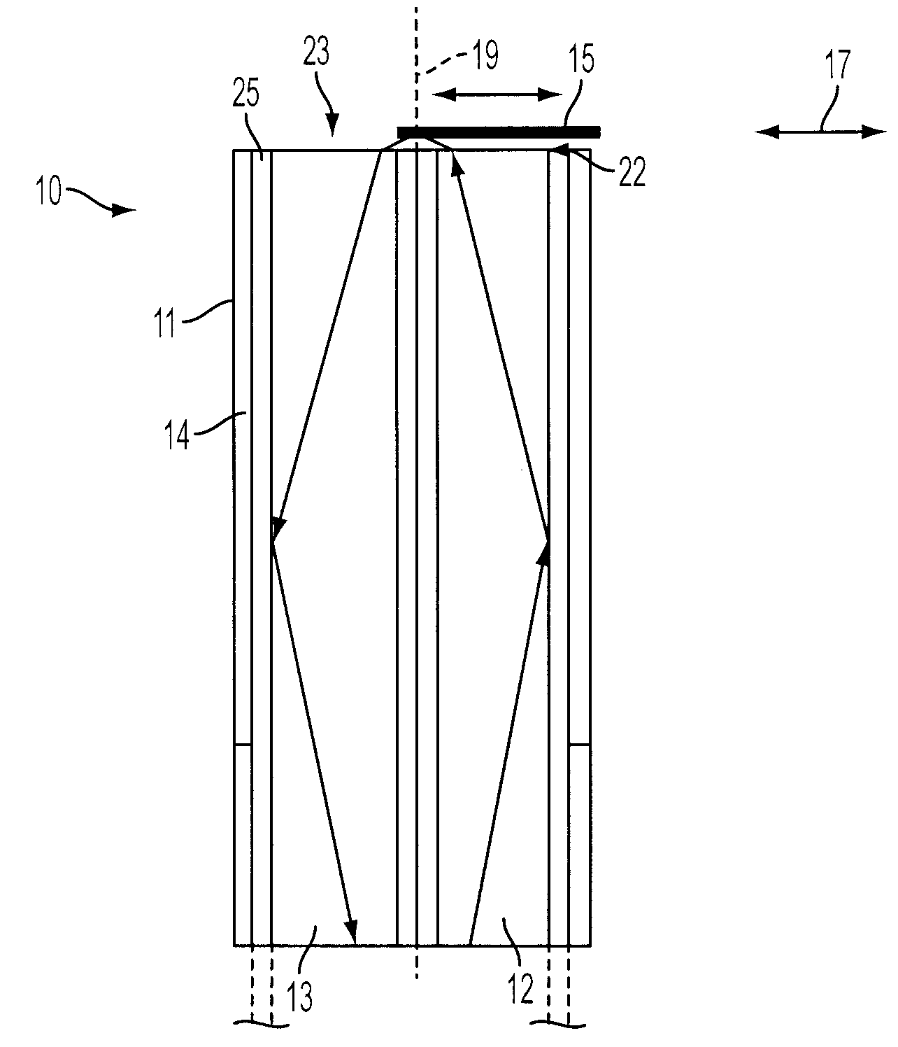
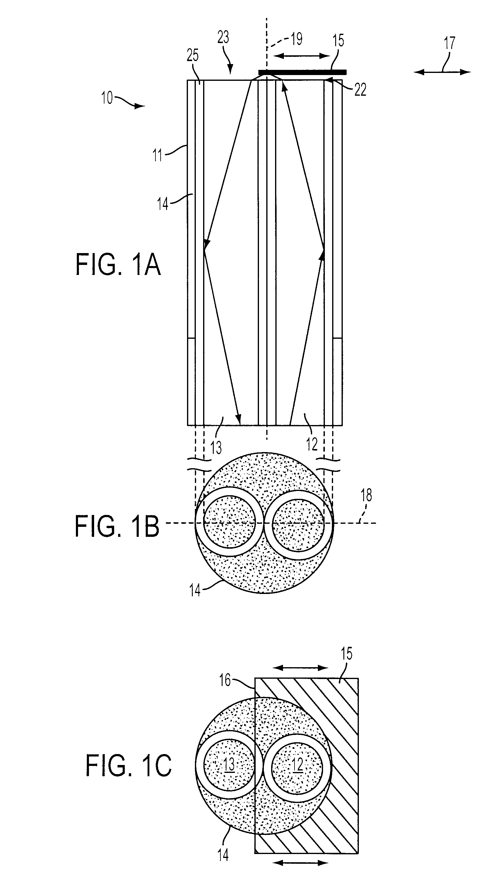
[0042]FIGS. 1A, 1B, and 1C illustrate basic principals of an intensity modulated fiber optic displacement and acceleration sensor 10 in accordance with an embodiment of the invention. The sensor 10 includes a fiber optic probe 11 having two multimode optical fibers, including a transmitting optical fiber 12 and a receiving optical fiber 13, each of which has a well polished fiber end 22 and 23. At the opposite end of the transmitting fiber 12 is a light emitting diode (LED) or other light source. A photodetector is positioned at the opposite end of the receiving fiber 13 for receiving light from the sensor 10 via the receiving fiber. Other components and connectors can be arranged between the LED, the sensor 10, and the photodetector.

[0043]As seen in FIG. 1B, the multimode optical fibers 12 and 13 each have a large core 24 and a cladding 25 with a lower index of refraction than that of the core. The two multimode optical fibers 12 and 13 are arranged within a housing 14, which can b...


PUM


Abstract

A fiber optic sensor for detecting acceleration or displacement includes a fiber optic probe with a multimode transmitting optical fiber, a multimode receiving optical fiber and a edge reflector spaced apart from the fiber probe. The reflector moves in a transverse direction substantially normal to the longitudinal axis of the fiber optic probe, so the amount of light received by the receiving fiber indicates a relative acceleration or a relative displacement of the reflective surface with respect to the fiber probe in the transverse direction of motion of the edge of the reflector. The reflector can be mounted on a cantilever beam. The sensor can have one transmitting fiber, two receiving fiber, and a reflector with two edges, each edge partially covering one of the receiving fibers. A triaxial sensor system has at least two two-fiber sensors.

Description

CROSS-REFERENCE TO RELATED APPLICATIONS[0001]This Application is a non-provisional of provisional (35 USC 119(e)) application 61 / 026,296 filed on Feb. 5, 2008, the disclosure of which is incorporated by reference herein in its entirety.BACKGROUND[0002]1. Technical Field[0003]This application is related generally to the field of sensors for displacement and acceleration, and more specifically, to fiber optic sensors for displacement and acceleration.[0004]2. Related Technologies[0005]Many commercially available accelerometers use a sensing element formed of PZT, which generates a small electrical current or voltage when acceleration is sensed. This small electrical signal is usually amplified. The PZT-based sensors typically require a bias electrical voltage for optimum performance. Such sensor systems can be bulky, expensive, and subject to electromagnetic interference. Remote control and multiplexing of these sensors can also be difficult.[0006]In recent years, fiber optic sensors ...

Claims


Application Information

Patent Timeline
Patent Type & Authority Applications(United States)
IPC IPC(8): G02B6/00
CPCG01D5/268G01D5/30G01P15/0802G01P15/093G02B6/3594G02B6/3552G02B6/3558G02B6/3566G02B6/3514G01P2015/0828
Inventor LAGAKOS, NICHOLASBUCARO, JOSEPH A.JARZYNSKI, JACEKJARZYNSKI, BARBARA
Owner THE UNITED STATES OF AMERICA AS REPRESENTED BY THE SECRETARY OF THE NAVY
Why Eureka
Try Eureka