Mounting and Positioning System

a positioning system and mounting bracket technology, applied in the field of mounting and positioning systems, can solve the problems of time-consuming and cumbersome process, easy drop and damage of cameras, and difficulty in removing cameras from mounting brackets, etc., and achieves the effect of convenient positioning, easy mounting, and easy positioning

Inactive Publication Date: 2009-08-06
AVAAK
View PDF3 Cites 75 Cited by
  • Summary
  • Abstract
  • Description
  • Claims
  • Application Information

AI Technical Summary

Benefits of technology

[0005]Briefly, the present invention provides a magnetic directional mount for easily mounting, positioning, and orienting an electronic device. The device may be a camera or other sensor device, or may be another directionally sensitive device such as a microwave or radio wave antenna. When constructed as a camera mount, the camera mount has a camera part that has an image sensor, electronics, battery, and communication components. The housing for the camera part has a generally concave mounting surface, with a magnet positioned inside the camera housing and adjacent to the camera mounting surface. A base part has a base mounting surface that is constructed to be attracted to the magnet. In one example, the base mounting surface is dome-shaped, with a convex curvature constructed to mate with the concave curvature of the camera mounting surface. The base part is mounted to a stable support, and the camera mounting surface brought near the base counting surface. The magnetic attractive forces pulls the camera part firmly to the base part, thereby securely positioning and orienting the camera. However, the camera may be readily repositioned by pushing the camera into a new position. The size and shape of the complementary mounting surfaces may be selected according to positioning requirements.
[0006]Advantageously, the mounting system provides a 3-dimension universal positioning mechanism for the camera or other electronic device. The camera may be easily attached or detached from its base part. Further, the camera may be easily adjusted for optimum positioning and orientation. Finally, because the camera mount system has no ball or joint structure, the camera may be freely moved into any position on the base mounting surface. It will be appreciated that the size and shape of the base mounting surface may be adjusted according to how much orientation flexibility is required. For example, the base mounting surface may be dome-shaped. The dome is typically a hemi-sphere or quarter-dome, but may be constructed to be nearly fully spherical in shape, thereby allowing a broader range of orientation. Similarly, if less flexibility is needed, the size and shape of the dome may be reduced.

Problems solved by technology

In this way, initially attaching a camera to a bracket often requires the use of tools, and can be a time consuming and cumbersome process.
For example, the camera is easily dropped and damaged during the installation process.
In a similar manner, removing a camera from its mounting bracket suffers from the same deficiencies.
In this way, repositioning cameras can also be a time consuming and cumbersome process.
In another disadvantage, the locking mechanism or the ball-andjoint structure may interfere with positioning, thereby limiting how the camera can be positioned.

Method used


Image

  • Mounting and Positioning System
  • Mounting and Positioning System
  • Mounting and Positioning System

Examples


Embodiment Construction

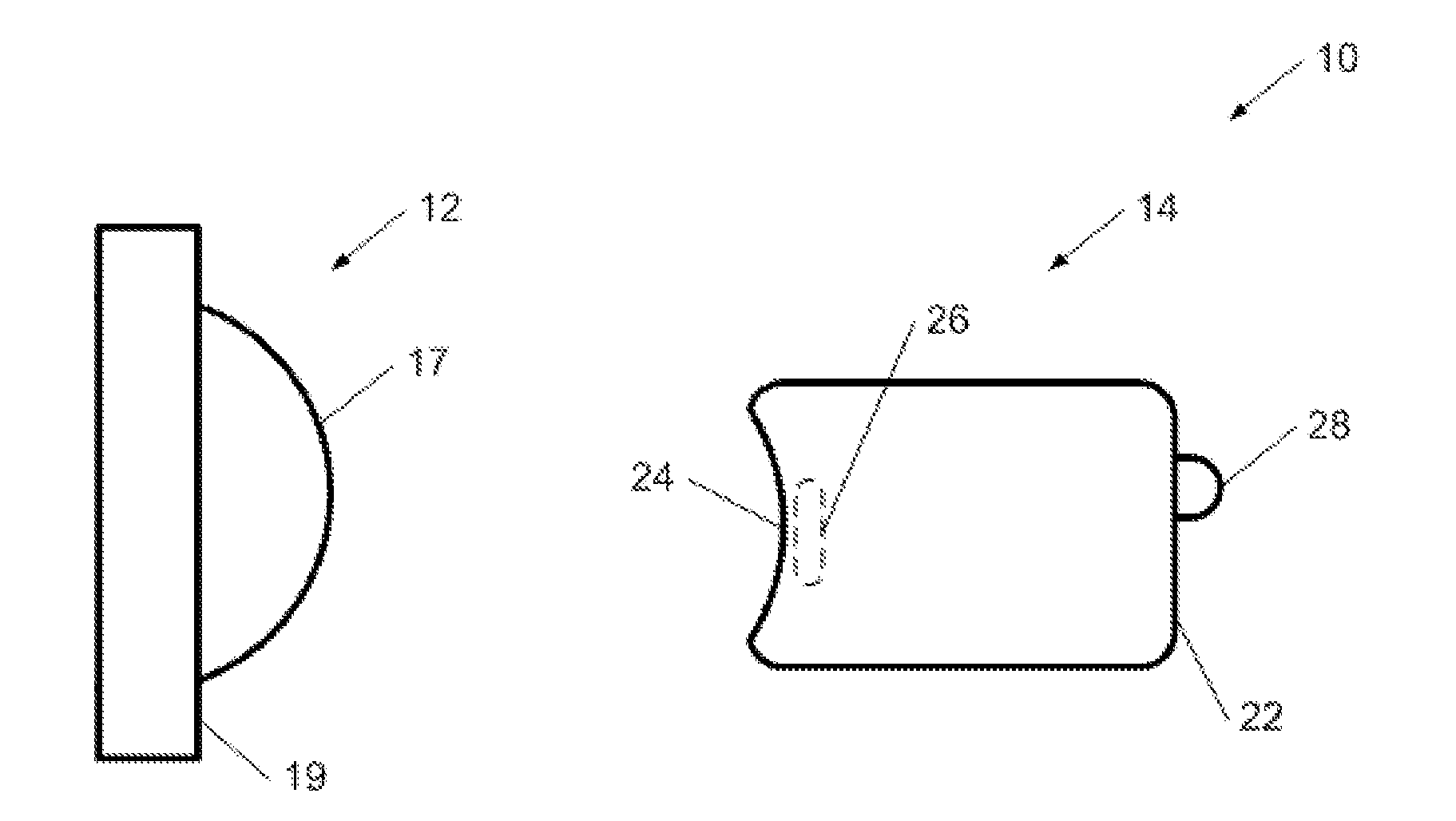
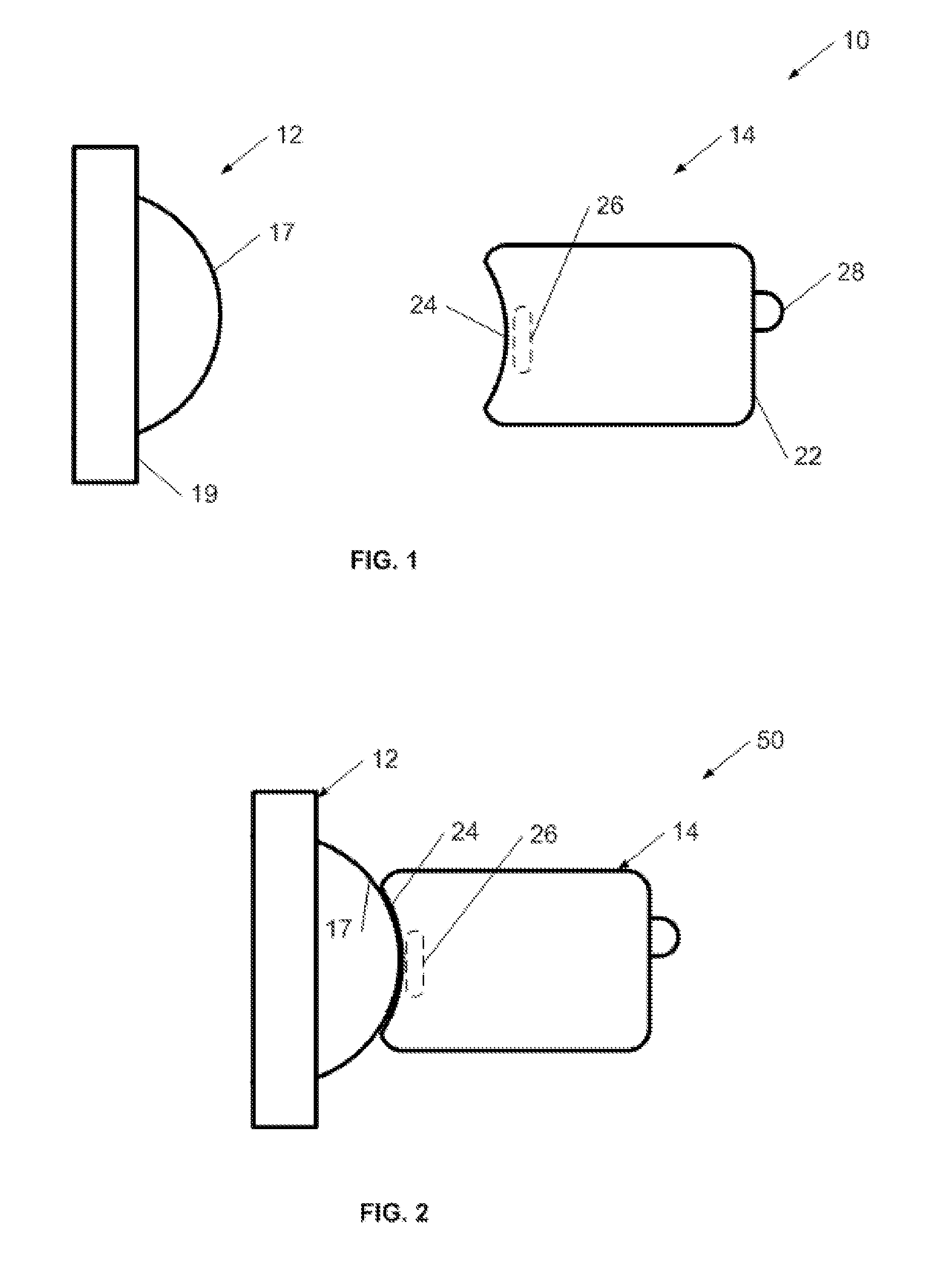
[0016]Referring now to FIG. 1, a directional mount system is illustrated. The directional mount system of FIG. 1 is shown in the form of a camera mount 10, but it will be appreciated that other types of mounts may be constructed. For example, the directional mount may be used for other types of image or video sensors, or may be used to mount directionally sensitive electronic devices such as microwave, satellite, or RF antennas. Camera mount system 10 may be used to advantageously and flexibly mount a camera to a supporting base. The camera may be a miniature camera, for example, like the camera described in co-pending U.S. application Ser. No. 11 / 847,471, entitled “Network Sensor System and Protocol”. It will be appreciated that other image or video cameras may be used. Camera mount system 10 comprises a base portion 12 and a cooperating camera portion 14. Base portion 12 has a convex surface 17 attached to a mounting base 19. Mounting base 19 is constructed to be securely attached...


PUM


Abstract

A magnetic mount is provided for easily mounting, positioning, and orienting a camera, sensor or other directionally sensitive electronic device. In one example the magnetic mount is a camera mount. The camera mount has a camera part that has an image sensor, electronics, battery, and communication components. The housing for the camera part has a generally concave mounting surface, with a magnet positioned inside the camera housing and adjacent to the camera mounting surface. A base part has a base mounting surface that is constructed to be attracted to the magnet. In one example, the base mounting surface is dome-shaped, with a convex curvature constructed to mate with the concave curvature of the camera mounting surface. The base part is mounted to a stable support, and the camera mounting surface brought near the base counting surface. The magnetic attractive forces pull the camera part firmly to the base part, thereby securely positioning and orienting the camera. However, the camera may be readily repositioned by pushing the camera into a new position. The size and shape of the complementary mounting surfaces may be selected according to positioning requirements.

Description

FIELD OF THE INVENTION[0001]The present invention relates to a mechanical device for mounting and positioning directionally sensitive electronic apparatus. In one example, the mount is constructed for holding and positioning a small camera.BACKGROUND[0002]The field of remote image capture is growing rapidly. Remote image capture has been found to be useful in security applications, as well as for monitoring environmental, commercial and industrial processes. In a typical remote imaging application, cameras are mounted in strategic positions in an area, and the cameras communicate image or video data to a central monitoring station. In one example, the remote imager is an Internet camera that communicates image data to a computer attached to the Internet. In another example, the remote imagers are miniature cameras that communicate on a private network. Once such camera and camera network is described in co-pending U.S. application Ser. No. 11 / 847,471, entitled “Network Sensor System...

Claims


Application Information

Patent Timeline
Patent Type & Authority Applications(United States)
IPC IPC(8): G03B17/00H04N7/18
CPCF16M11/14H04N5/2252G03B17/00F16M13/02H04N23/51
Inventor MESSINGER, GIOIAPAUL, ANDREWZOOLAKIS, ANDREW
Owner AVAAK
Why Eureka
Try Eureka