

Method for making coaxial cable
- Summary
- Abstract
- Description
- Claims
- Application Information
AI Technical Summary
Benefits of technology
Problems solved by technology
Method used
Image

Examples
Embodiment Construction
[0022]References will now be made to the drawings to describe, in detail, embodiments of the present coaxial cable and method for making the same.
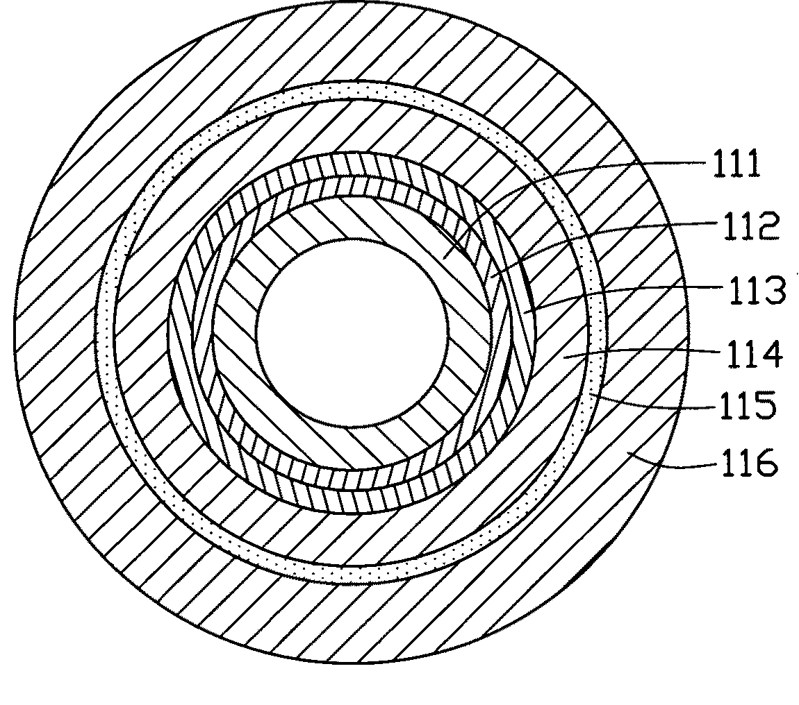
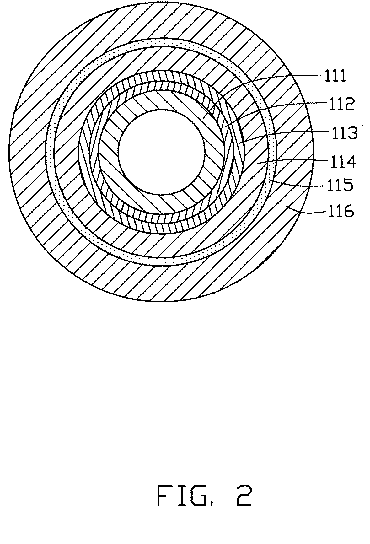
[0023]The coaxial cable includes at least one core, at least one insulating layer, at least one shielding layer, and a sheathing layer.
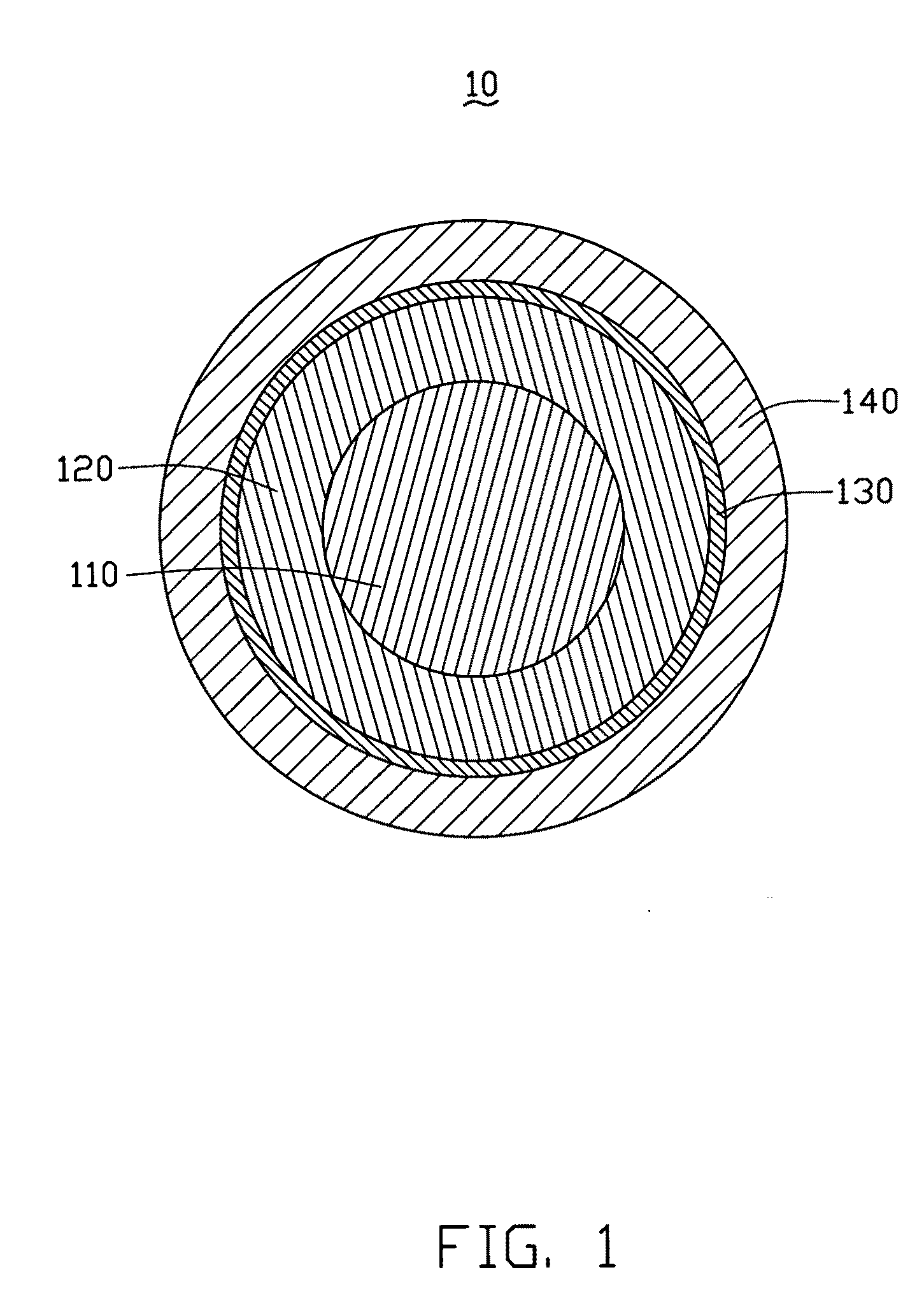
[0024]Referring to FIG. 1, a coaxial cable 10 according to a first embodiment includes a core 110, an insulating layer 120, a shielding layer 130, and a sheathing layer 140. The insulating layer 130 wraps the core 110. The shielding layer 130 wraps the insulating layer 120. The sheathing layer 140 wraps the shielding layer 130. The core 110, the insulating layer 120, the shielding layer 130, and the sheathing layer 140 are coaxial.
[0025]The core 110 includes at least one carbon nanotube wire-like structure. The wire-like structure means that the structure has a large ratio of length to diameter. Specifically, the core 110 includes a single carbon nanotube wire-like structure or a plurality of carbon nanotub...
PUM
| Property | Measurement | Unit |
|---|---|---|
| Thickness | aaaaa | aaaaa |
| Thickness | aaaaa | aaaaa |
| Structure | aaaaa | aaaaa |
Abstract
Description
Claims
Application Information