Valve piston repositioning apparatus and method

a valve piston and repositioning technology, applied in mechanical equipment, metal working equipment, manufacturing tools, etc., can solve the problems of deformation or failure of the booster valve, wear of the booster valve sleeve, and deformation of the booster valve performance, so as to prolong the life of the booster valv

Inactive Publication Date: 2009-08-13
YOUNGER STEVEN W
View PDF47 Cites 12 Cited by
  • Summary
  • Abstract
  • Description
  • Claims
  • Application Information

AI Technical Summary

Benefits of technology

[0004]The present invention addresses the above and other needs by providing apparatus and method for extending the life of a booster valve in an automatic transmission. The booster valve commonly resides in the pump stator body and is modulated by reverse oil pressure and pressure control solenoid pressure signals. Pressure signals from the reverse oil pressure and the pressure control solenoid force a booster valve piston towards a pressure regulator valve piston also generally residing in the pump stator body. The booster valve piston slides inside a booster valve sleeve, and over time, the booster valve sleeve wears and the performance of the booster valve degrades or fails. The present invention replaces an original inner booster valve (or bumper) spring with a longer (or in some cases shorter) replacement booster valve spring to shift the operating range of the booster valve piston to an unworn portion of the booster valve sleeve to extend the life of the booster valve.

Problems solved by technology

The booster valve piston slides inside a booster valve sleeve, and over time, the booster valve sleeve wears and the performance of the booster valve degrades or fails.

Method used


Image

  • Valve piston repositioning apparatus and method
  • Valve piston repositioning apparatus and method
  • Valve piston repositioning apparatus and method

Examples


Embodiment Construction

[0019]The following description is of the best mode presently contemplated for carrying out the invention. This description is not to be taken in a limiting sense, but is made merely for the purpose of describing one or more preferred embodiments of the invention. The scope of the invention should be determined with reference to the claims.

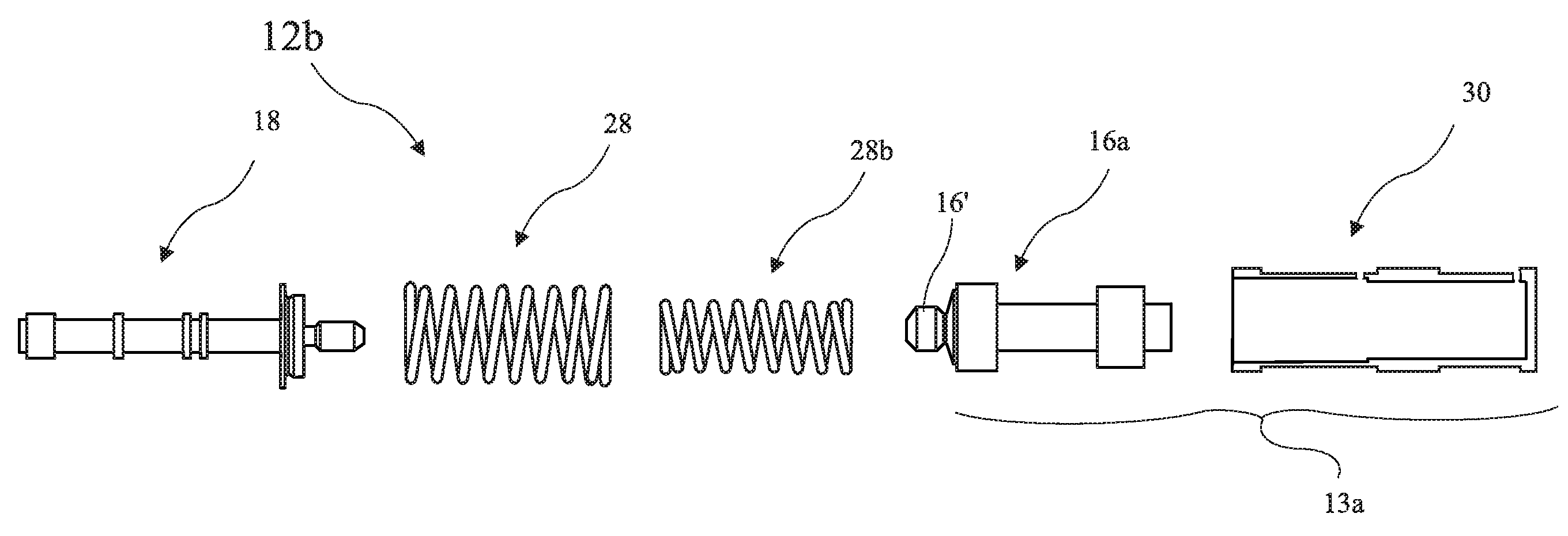
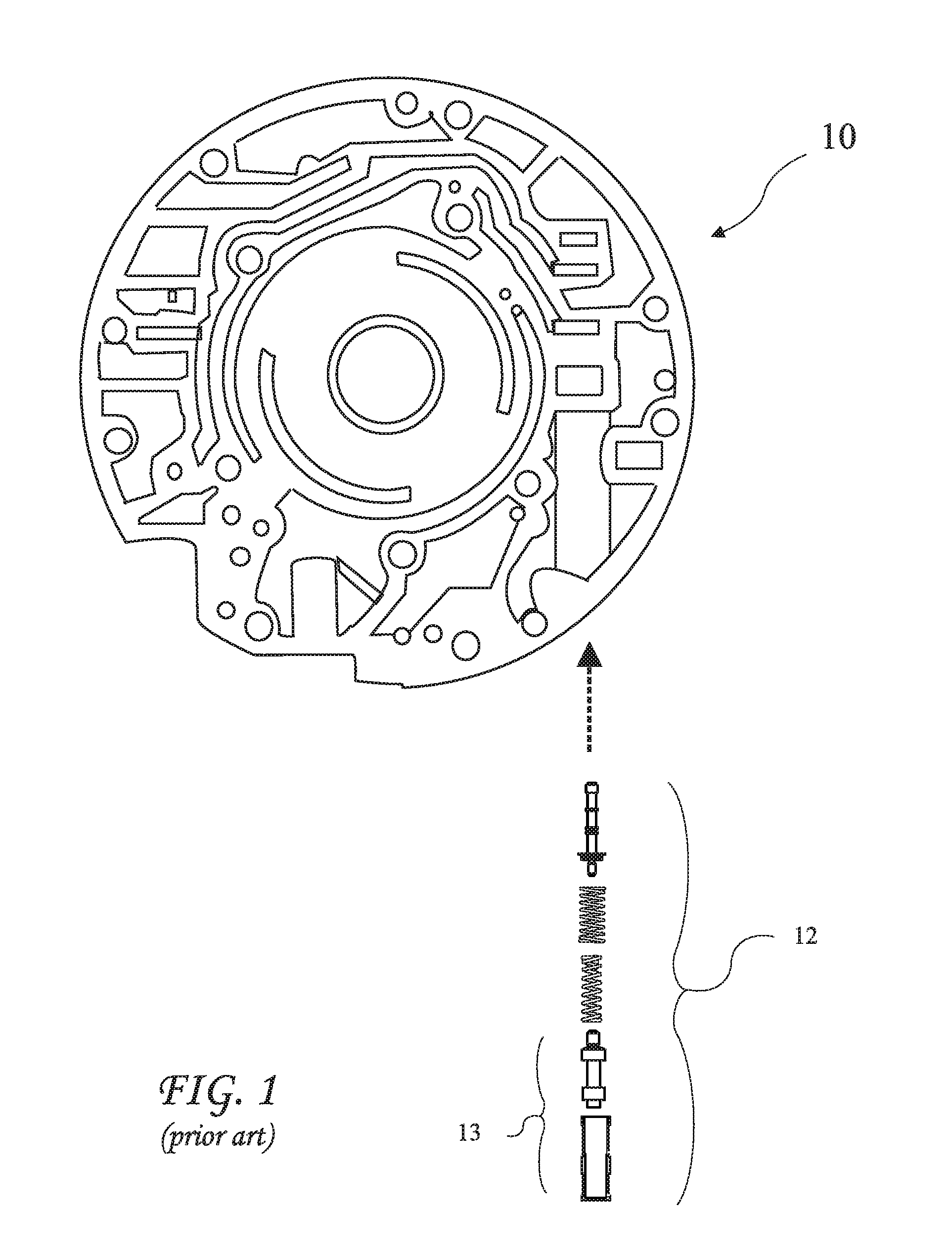
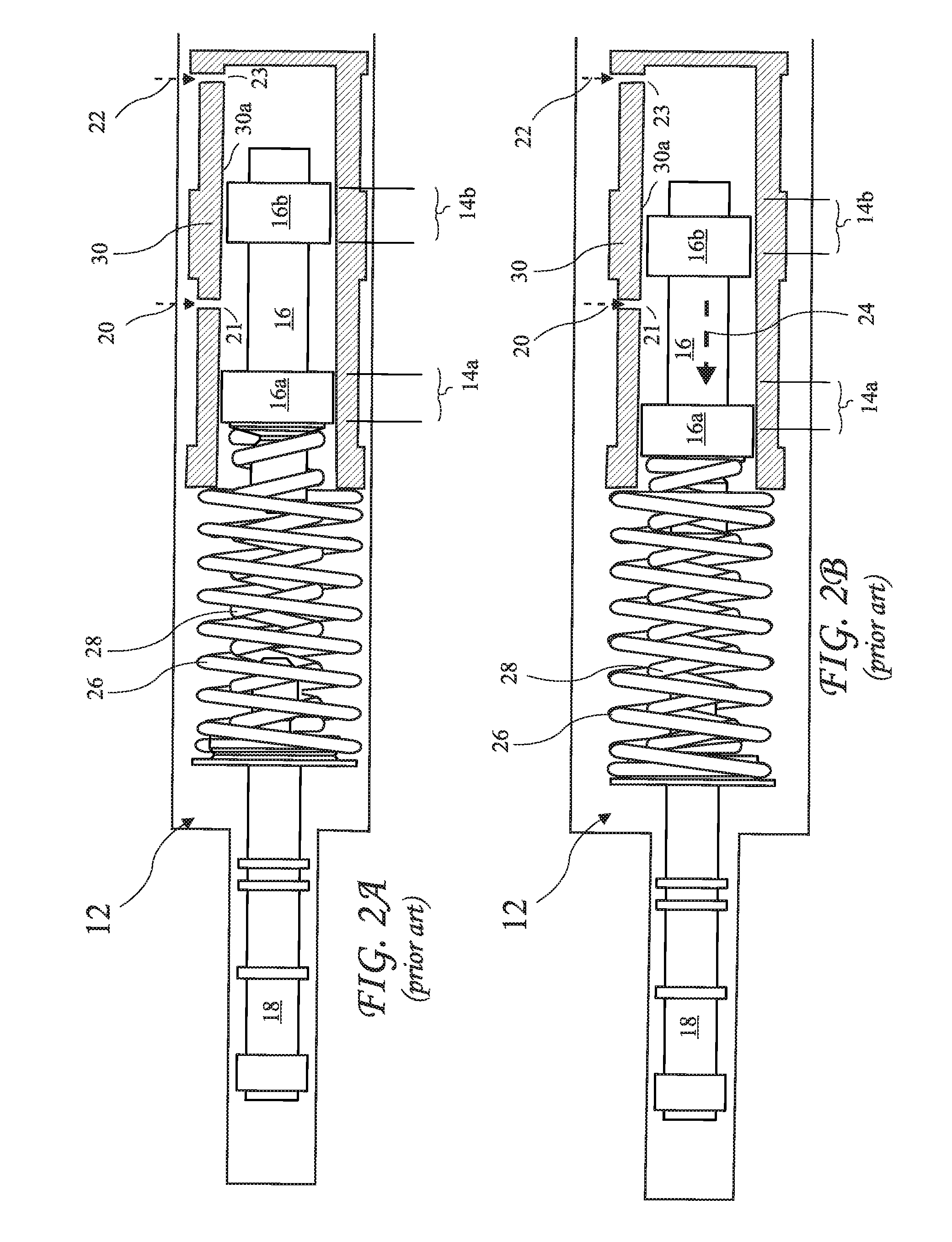
[0020]A prior art automatic transmission pump stator body 10 and exploded booster valve and pressure regulator valve assembly 12 are shown in FIG. 1. The booster valve and pressure regulator valve assembly 12 normally resides in the automatic transmission pump stator body 10 and controls an automatic transmission fluid pressure in response to reverse and pressure control solenoid pressure signals. The booster valve and pressure regulator valve assembly 12 includes a booster valve assembly 13 controlled by pressure signals 20 and 22 through ports 21 and 23 respectively (see FIG. 2A).

[0021]The booster valve and pressure regulator valve assembly 12 i...


PUM

PropertyMeasurementUnit
lengthaaaaaaaaaa
diameteraaaaaaaaaa
diameteraaaaaaaaaa

Abstract

Apparatus and method for extending the life of a booster valve in an automatic transmission. The booster valve commonly resides in the pump stator body and is modulated by reverse oil pressure and pressure control solenoid pressure signals. Pressure signals from the reverse oil pressure and the pressure control solenoid force a booster valve piston towards a pressure regulator valve piston also generally residing in the pump stator body. The booster valve piston slides inside a booster valve sleeve, and over time, the booster valve sleeve wears and the performance of the booster valve degrades or fails. The present invention replaces an original inner booster valve spring with a longer (or in some cases shorter) replacement booster valve spring to shift the operating range of the booster valve piston to an unworn portion of the booster valve sleeve to extend the life of the booster valve.

Description

BACKGROUND OF THE INVENTION[0001]The present invention relates to valve repair and in particular to apparatus and methods for extending the life of an automatic transmission valve by modifying the valve to shift a valve piston from a worn region of a valve sleeve to an unworn region of the valve sleeve.[0002]Automatic transmissions are commonly used in cars and trucks. Such automatic transmissions rely on a pump and system of valves to route a fluid flow to selectively lock and unlock gears to control the overall gear ratio through the transmission. The valves wear over time and eventually fail requiring service. The cost of replacing entire valve bodies can be quite high, and as a result, methods for repairing existing valve bodies have been developed.[0003]U.S. Pat. No. 6,832,632 for “Boost Valve Assembly,” discloses a direct replacement booster valve assembly to replace a worn booster valve. The replacement valve of the '632 patent includes a new hard-anodized booster valve pisto...

Claims


Application Information

Patent Timeline
Patent Type & Authority Applications(United States)
IPC IPC(8): B23P6/00
CPCF15B13/0402F16H61/0276F16H2061/0253Y10T29/53443Y10T29/49407Y10T29/49723Y10T29/53565Y10T29/49229Y10T29/4925Y10T29/53617Y10T29/49726Y10T29/53474
Inventor YOUNGER, STEVEN W.
Owner YOUNGER STEVEN W
Why Eureka
Try Eureka