Methods to protect selective catalyst reducer aftertreatment devices during uncontrolled diesel particulate filter regeneration

a selective catalyst and aftertreatment device technology, applied in mechanical equipment, machines/engines, electric control, etc., can solve the problems of premature aging and failure of the catalyst reducer, and achieve the effect of improving the results

Inactive Publication Date: 2009-08-13
DETROIT DIESEL CORP
View PDF28 Cites 26 Cited by
  • Summary
  • Abstract
  • Description
  • Claims
  • Application Information

AI Technical Summary

Benefits of technology

[0016]Whereas the methods of the present invention are useful and operational at all modes...

Problems solved by technology

In systems where the DPF is located upstream of a urea SCR catalyst, any uncontrolled regenerations or...

Method used


Image

  • Methods to protect selective catalyst reducer aftertreatment devices during uncontrolled diesel particulate filter regeneration
  • Methods to protect selective catalyst reducer aftertreatment devices during uncontrolled diesel particulate filter regeneration
  • Methods to protect selective catalyst reducer aftertreatment devices during uncontrolled diesel particulate filter regeneration

Examples


Embodiment Construction

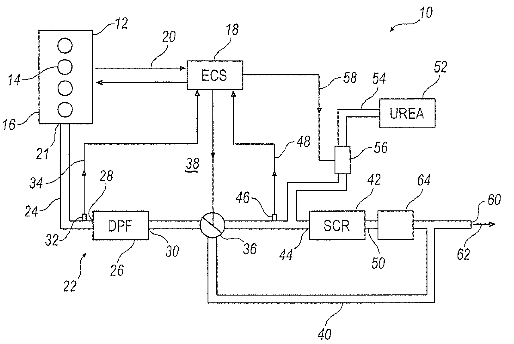
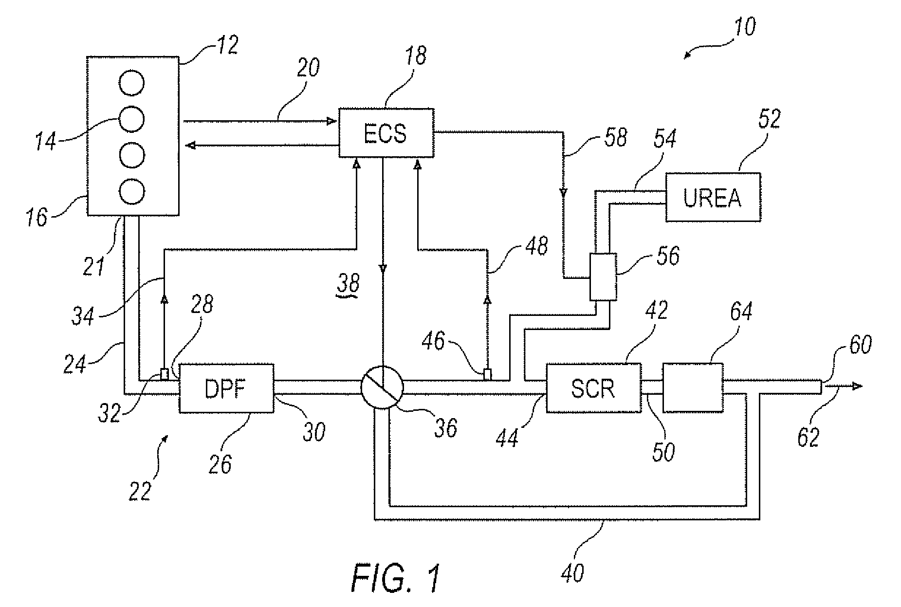
[0019]Turning now to the drawings wherein like numbers refer to like structures, vehicle system 10 includes internal combustion engine 12 having cylinders 14 disposed within block 16 for reciprocal movement therein. The engine may be of any construction, such as a spark ignition engine or a compression ignition engine, and is preferably a compression ignition type engine. The engine is electronically controlled by an Engine Control System 18 (ECS) that may be comprised of a single module or multiple modules, as is well known in the art. The ECS has memory, such as PROM, EPROM, EEPROM, FLASH, volatile and nonvolatile memory, and may also have tables or maps therein within which are loaded operating instructions and other information necessary for the operation and control of the engine and any system. In a preferred embodiment, the Engine Control System has DDEC operating instructions and programs loaded therein such as is available from Detroit Diesel Corporation. The ECS communicat...


PUM


Abstract

The present invention is directed to a method to operate an electronically controlled internal combustion engine with an exhaust system equipped with a diesel particulate filter upstream of a selective catalyst reducer to protect the selective catalyst reducer from premature aging and failure caused by exhaust temperature heat generated during uncontrolled regeneration of the diesel particulate filter.

Description

TECHNICAL FIELD[0001]On diesel engines requiring both NOx and particulate aftertreatment systems, it is likely that some systems will use both urea selective catalytic reducers (SCR) in combination with diesel particulate filters (DPF). In systems where the DPF is located upstream of a urea SCR catalyst, any uncontrolled regenerations or other high temperature excursions in the DPF could also put the SCR at risk of premature aging and failure. In systems where the DPF is upstream of the SCR, this is especially a factor. There is a need to protect the SCR during periods of uncontrolled DPF regeneration to ensure SCR long service life and prevent premature aging and failure caused by exposure to high heat.BRIEF SUMMARY OF THE INVENTION[0002]In one embodiment, the present invention is directed to a method to operate an electronically controlled internal combustion engine equipped with a Engine Control System (ECS) and an exhaust system with a Diesel Particulate Filter (DPF) having an i...

Claims


Application Information

Patent Timeline
IPC IPC(8): F01N3/023F01N3/035
CPCF01N3/035F01N3/106F01N3/2053F01N3/208F01N2410/02F01N13/009F01N2610/02F01N2900/1602F02D41/08Y02T10/24F01N2560/06Y02T10/12
Inventor SISKEN, KEVIN D.BAIRD, MATTHEW T.
Owner DETROIT DIESEL CORP
Why Eureka
Try Eureka