Air-cooled engine

Active Publication Date: 2009-08-13
HONDA MOTOR CO LTD
View PDF2 Cites 10 Cited by
  • Summary
  • Abstract
  • Description
  • Claims
  • Application Information

AI Technical Summary

Benefits of technology

[0010]Since the bolts are disposed outside of the valve compartment, the bolts need not be placed-inside the valve chamber. The size of the valve compartment can be reduced inasmuch as no space need be provided to place the bolts inside the valve chamber, and the air-cooled engine can thereby be reduced in size.
[0011]Furthermore, a smaller valve compartment makes it possible to increase the surface area of the part of the cylinder head in which the area in the vicinity of the combustion chamber is exposed, i.e., the radiating surface area. Moreover, since the valve compartment is smaller, the distance from the outer surface of the valve compartment to the combustion chamber can be reduced. Cooling air can therefore be conducted to the vicinity of the combustion chamber. As a result, the area of the cylinder head that surrounds the combustion chamber can be cooled more adequately, and cooling efficiency can be improved.
[0012]The air-cooled engine preferably further comprises a power transmission mechanism for transmitting drive force from the crankshaft to the camshaft, and a transmission mechanism compartment for accommodating the power transmission mechanism, wherein at least part of the transmission mechanism compartment is formed in the cylinder head so as to be separated from the valve compartment. Adequate space can therefore be provided to allow cooling air to pass between the valve compartment and the transmission mechanism compartment. The effects of cooling the cylinder head are further improved by the passage of

Problems solved by technology

Reducing the size of the air-cooled engine is therefore limited.
Therefore, with a large valve chamber, part of the combustion cham

Method used


Image

  • Air-cooled engine
  • Air-cooled engine
  • Air-cooled engine

Examples


Embodiment Construction

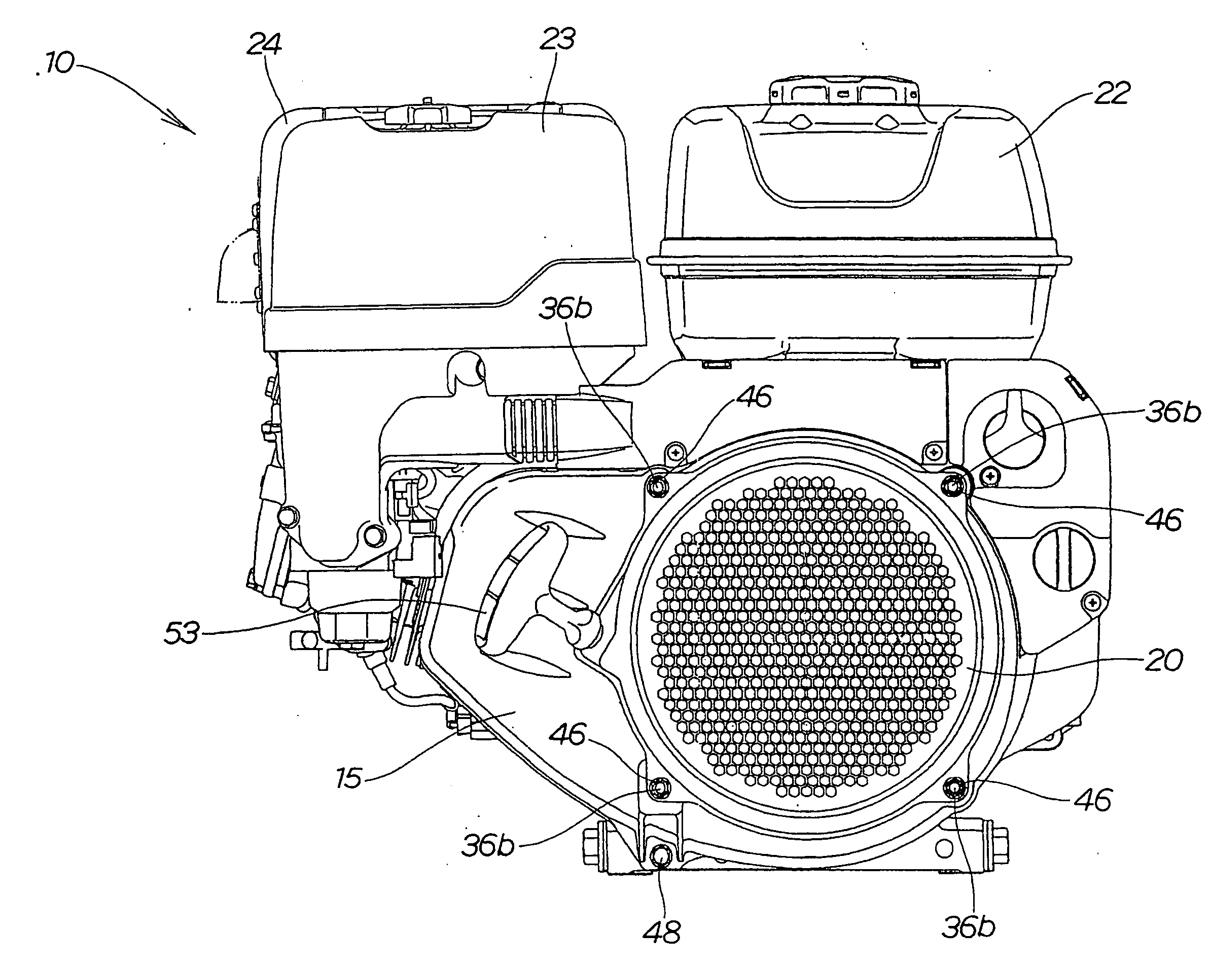
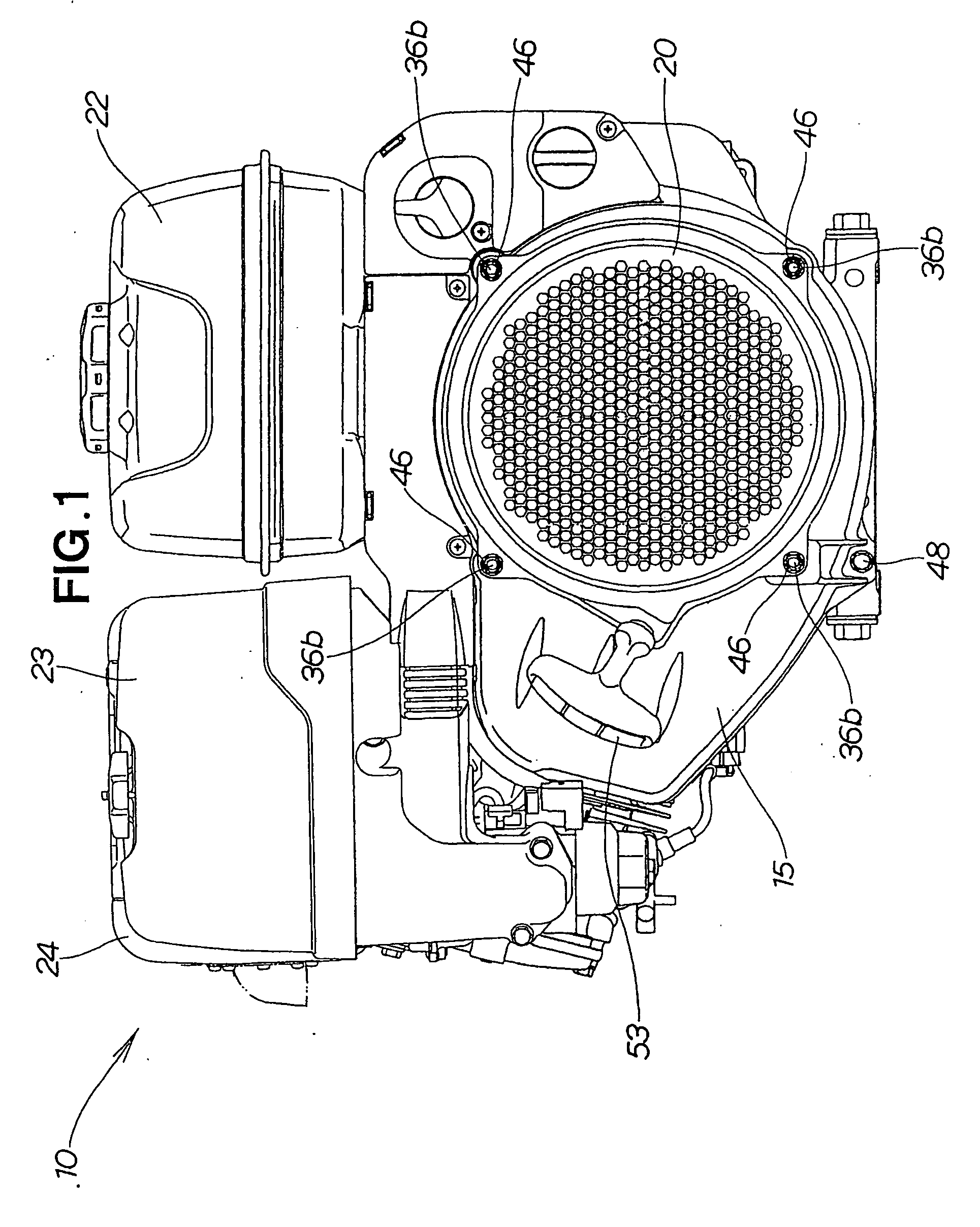
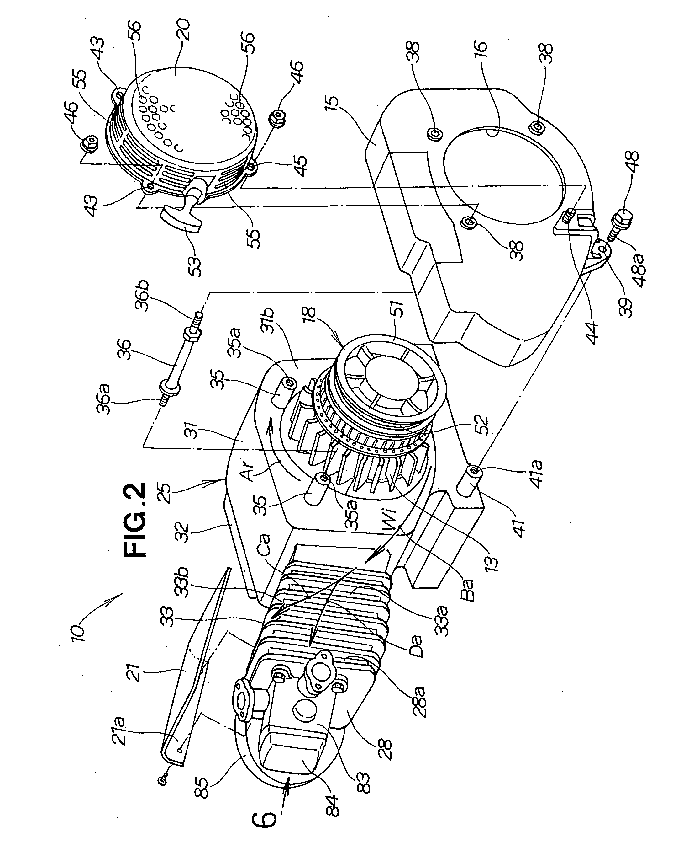
[0029]As shown in FIGS. 1 and 2, the air-cooled engine 10 is an OHC (overhead-cam) single-cylinder engine having a tilted cylinder. The engine and comprises a cooling fan 13, a fan cover 15 that covers the cooling fan 13, a recoil starter 18, a starter cover 20 that covers the recoil starter 18, a fuel tank 22, an air cleaner 23, and a muffler 24.

[0030]As shown in FIG. 2, the cooling fan 13 and the recoil starter 18 are linked with a crankshaft 12 (see FIG. 3). The fan cover 15 has an opening 16 through which the recoil starter 18 passes.

[0031]As shown in FIGS. 2 and 3, the air-cooled engine 10 includes the crankshaft 12, a casing 25, a cylinder 26, and a cylinder head 28.

[0032]The casing 25 is composed of a crank case 31, a case cover 32 that closes off the opening 31a of the crank case 31, and a cylinder block 33 formed integrally on the side of the crank case 31 (the left end in FIG. 2).

[0033]The crank case 31 rotatably accommodates the crankshaft 12. The opening 31a of the crank...


PUM


Abstract

There is provided an air-cooled engine (10) that is cooled by cooling air. The air-cooled engine (10) comprises a cylinder block (33), and a cylinder head (28) that closes off one end of a cylinder (26). The cylinder head (28) includes a base part (81) that is superposed on and secured to the cylinder block (33) by a plurality of bolts (91), and a valve compartment (83) formed integrally on the base part (81). All of the bolts (91) are disposed near the outer periphery of the base part (81) at positions outside of the valve compartment (83).

Description

TECHNICAL FIELD[0001]The present invention relates to an air-cooled engine wherein a cylinder head is fastened to a cylinder block with bolts.BACKGROUND ART[0002]In some air-cooled engines, the cylinder head is provided with a valve chamber for accommodating an intake valve and an exhaust valve, and the cylinder head is superposed on the cylinder block and is fastened on with bolts. This type of air-cooled engine is disclosed in Japanese Examined Utility Model Application No. 2-32849.[0003]The air-cooled engine disclosed in Japanese Examined Utility Model Application No. 2-32849 is a multipurpose engine wherein a cylinder head provided with a valve chamber and a cooling air duct is superposed on and bolted to the cylinder block. The cylinder head includes three mounting holes disposed inside the valve chamber (valve compartment), and two mounting holes disposed outside the valve chamber. Bolts passed through these five mounting holes are screwed into the cylinder block, whereby the ...

Claims


Application Information

Patent Timeline
IPC IPC(8): F02F1/34F01P1/00
CPCF01P1/02F02B2275/18F02F2007/0041F02F1/32F02F1/24
Inventor SATO, YOSHIKAZUHONDA, SOUHEI
Owner HONDA MOTOR CO LTD
Why Eureka
Try Eureka