Heating cooker having drawer type automatic door

a technology of automatic door and cooking pot, which is applied in the field of microwave ovens, can solve the problems of large force being applied to the door, the inability to heat food normally, and the inability to fall or overflow soup or the like, etc., and achieve the effect of reducing the noise generated at the time of shocking and greatly changing the weight of the drawer body

Active Publication Date: 2009-08-13
SHARP KK
View PDF3 Cites 14 Cited by
  • Summary
  • Abstract
  • Description
  • Claims
  • Application Information

AI Technical Summary

Benefits of technology

[0020]Since the cooking device having a drawer type automatic door in accordance with the present invention is configured as described above, in stopping the drawer body, the speed control is carried out from the before-stop position detected by the specific position detecting means. As a result, even if the weight of the drawer body is changed greatly, by carrying out delicate control before stopping, the influence (falling, overflowing, or the like) exerted on a food by a shock produced by stopping at the t

Problems solved by technology

However, in the conventional cooking device having an automatic door, in the case where an object of the cooking is a liquid or a liquid object put in a cup or a soup put in a soup plate having a shallow depth, when the object is accommodated in the heating chamber or taken out of the heating chamber, if the door is opened or closed at a fixed speed, there is a possibility of falling of the cup or overflowing of the soup or the like.
Therefore, even in the case where the door is opened or closed automatically, when the door is stopped, a large force tends to be applied to the door.
At this time, a positional error is produced in the position control, and also a great acceleration is

Method used


Image

  • Heating cooker having drawer type automatic door
  • Heating cooker having drawer type automatic door
  • Heating cooker having drawer type automatic door

Examples


Embodiment Construction

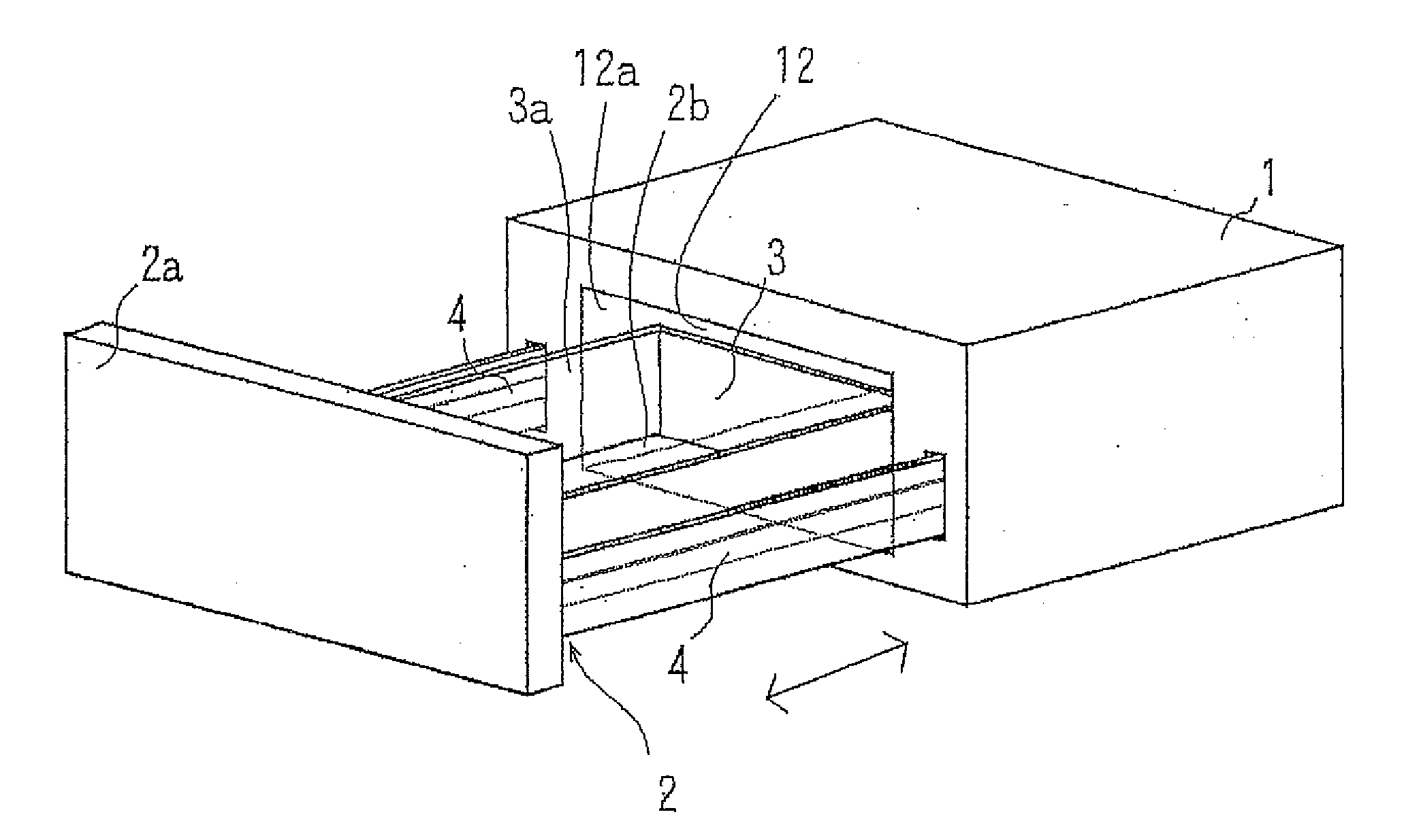
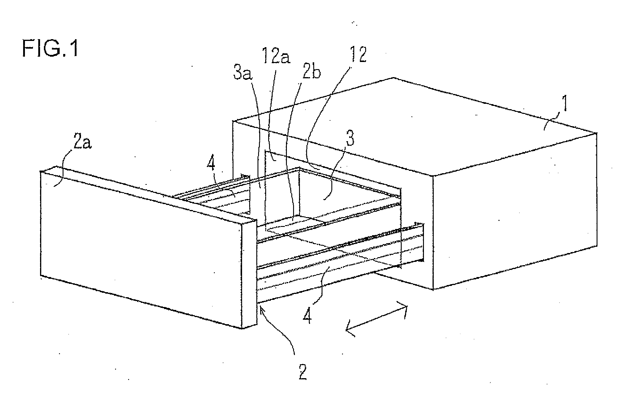
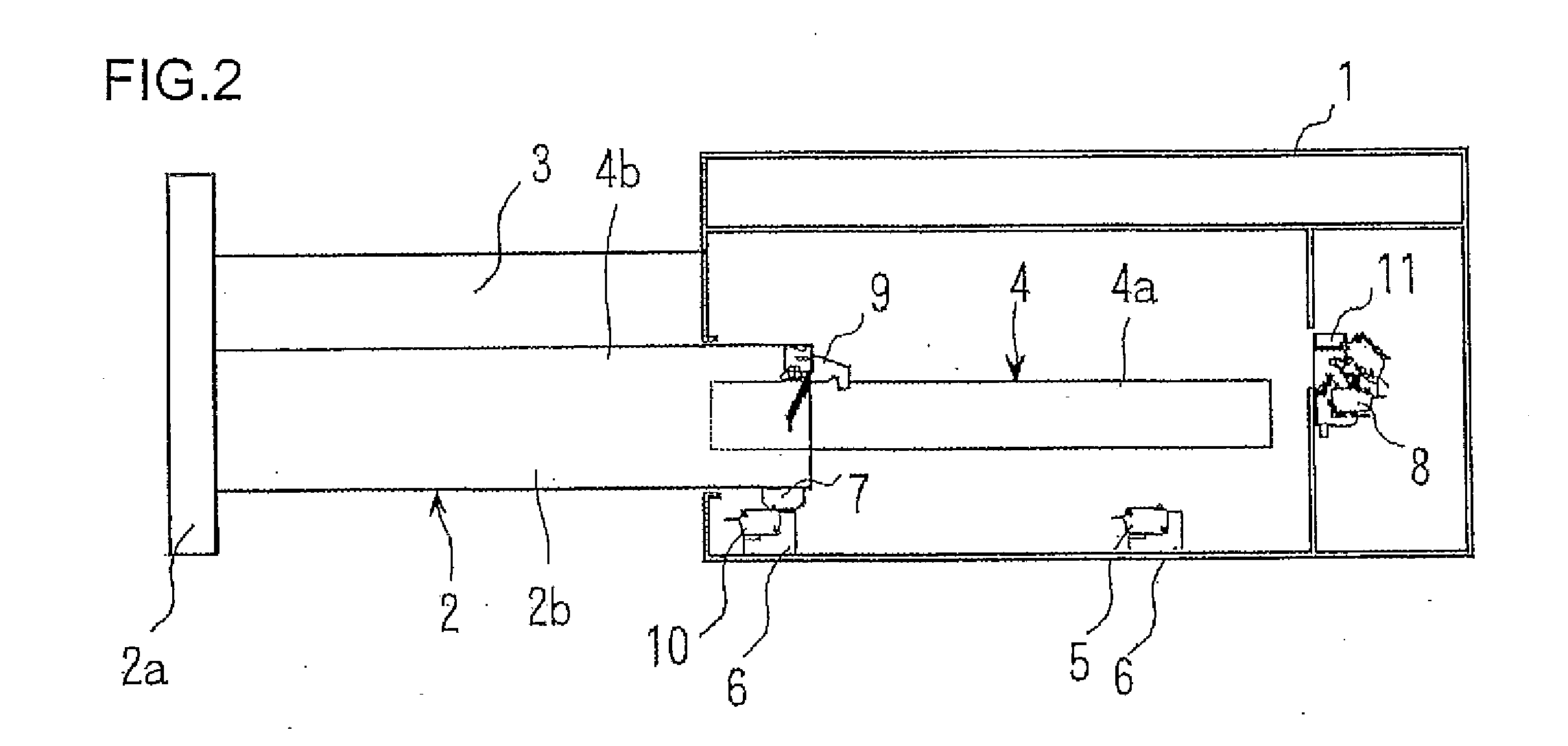
[0026]An embodiment of a cooking device having a drawer type automatic door (hereinafter referred simply to as a “cooking device”) in accordance with the present invention will now be described with reference to the accompanying drawings. FIG. 1 is a perspective view showing the outline of the cooking device in accordance with the present invention, showing a state in which the door is open. FIGS. 2 to 4 are side sectional views of the cooking device shown in FIG. 1, FIG. 2 showing a state in which the door is fully opened, FIG. 3 showing a state in which the door is at a deceleration position, and FIG. 4 showing a state in which the door is fully closed.

[0027]As shown in FIG. 1, the cooking device includes a cooking device body 1 and a drawer body 2 on which an object to be heated is placed together with an accommodation container for the object and which can be drawn out of and accommodated in the cooking device body 1. In the cooking device body 1, a heating chamber 12 in which t...


PUM


Abstract

There is provided a cooking device having a drawer type automatic door in which delicate control is carried out when the door is opened and closed, whereby an influence (falling, overflowing, or the like) exerted on an object to be cooked such as a food by a shock produced at the time of door opening and closing can be reduced or eliminated. When a before-stop position (full opening detection switch Pso at the time of full opening, intermediate switch Psi at the time of full closing) provided before the stop position of the door is detected by specific position detecting means, speed control means controls driving means to reduce the travel speed of a drawer body. For the door opening and closing at the time of start and finish of cooking, a position at which the drawer body is to be stopped automatically (fully opened position Po, fully closed position Pc) is recognized, and the opening/closing speed leading to the stopping is controlled. Therefore, the sudden stop of the drawer body at the stop position is prevented, and the degree of shock at the time of stopping is restrained, by which the influence on the object to be cooked such as a food can be reduced or eliminated.

Description

[0001]The present application is based on Japanese patent application No. 2006-197244 filed on Jul. 19, 2006, the entire contents of which are hereby incorporated by reference.BACKGROUND OF THE INVENTION[0002]In the field of microwave oven, new distinct configuration of automatic drawer type is emerging of late, for which this invention is intended for a further improvement.[0003]Up to now, the engineers in charge of drawer type microwave oven anticipated implementing practices of manual drawer operation.[0004]To name an example, if the automatic operation of the drawer is allowed to stop flat and hard at the end of opening operation, it might jerk the soup plate or topple the beverage mug to cause spillage to the disappointment of the customer.[0005]This invention is intended to minimize the disappointment in this respect.[0006]1. Field of the Invention[0007]The present invention relates to a cooking device having a drawer type automatic door, such as a microwave oven, provided wit...

Claims


Application Information

Patent Timeline
IPC IPC(8): H05B6/68F24C7/02F24C15/02
CPCF24C7/087F24C15/162H05B6/6414
Inventor MYOJI, TOSHIRO
Owner SHARP KK
Why Eureka
Try Eureka