
Boundary acoustic wave device manufacturing method and boundary acoustic wave device

a manufacturing method and technology of acoustic waves, applied in the direction of piezoelectric/electrostrictive device details, magnetic bodies, instruments, etc., can solve the problem of not having a known effective method for adjusting frequency characteristics after manufacturing, and achieve the effect of high accuracy

Active Publication Date: 2009-08-13
MURATA MFG CO LTD
View PDF9 Cites 12 Cited by
  • Summary
  • Abstract
  • Description
  • Claims
  • Application Information

AI Technical Summary

Benefits of technology

[0014]In light of the circumstances described above, preferred embodiments of the present invention provide a boundary acoustic wave device manufacturing method and a resulting boundary acoustic wave device that enable frequency characteristics to be adjusted with high accuracy.

Problems solved by technology

However, in the boundary acoustic wave device, an IDT electrode is embedded at an interface between first and second solid media and there is no space to which the IDT electrode is exposed.
There is no known effective method for adjusting frequency characteristics after manufacturing.

Method used


Image

  • Boundary acoustic wave device manufacturing method and boundary acoustic wave device
  • Boundary acoustic wave device manufacturing method and boundary acoustic wave device
  • Boundary acoustic wave device manufacturing method and boundary acoustic wave device

Examples


Embodiment Construction

[0042]The present invention is described below using explanation of specific preferred embodiments of the present invention with reference to the drawings.

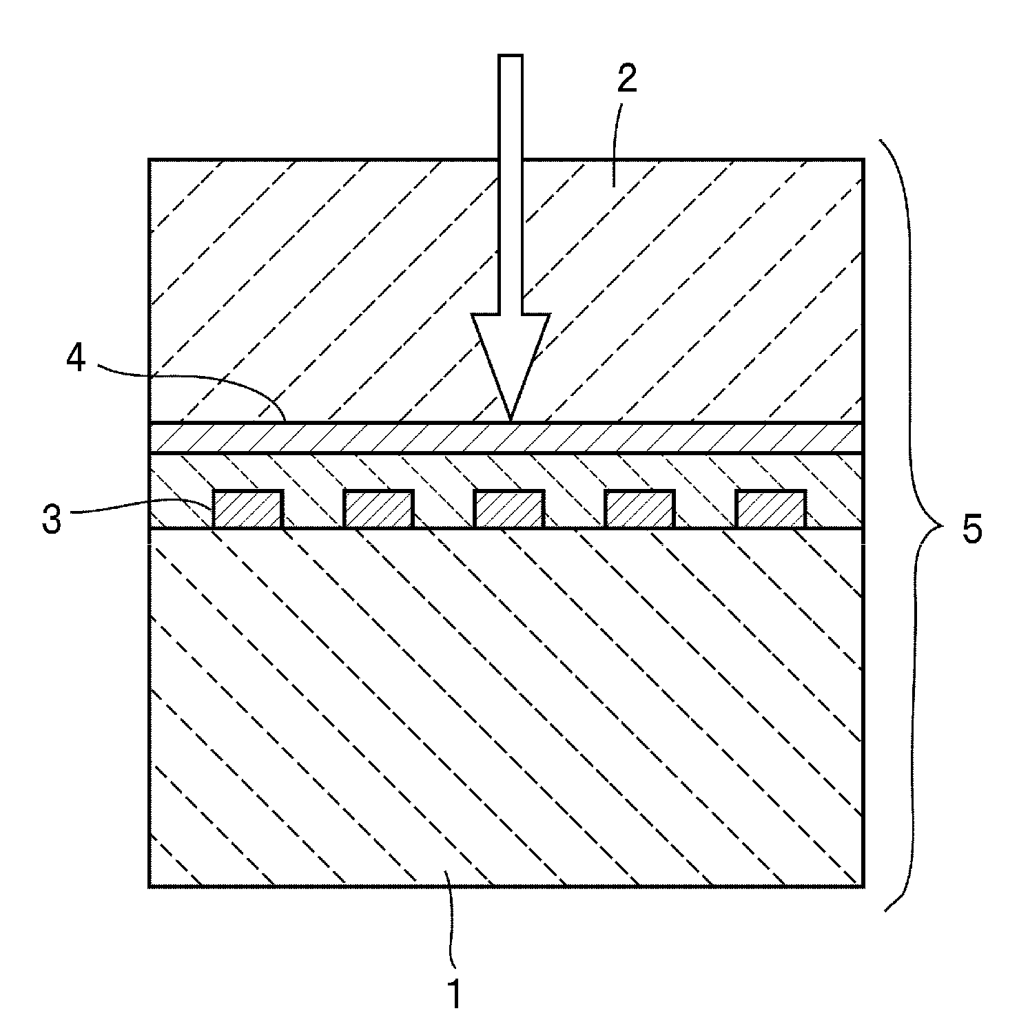
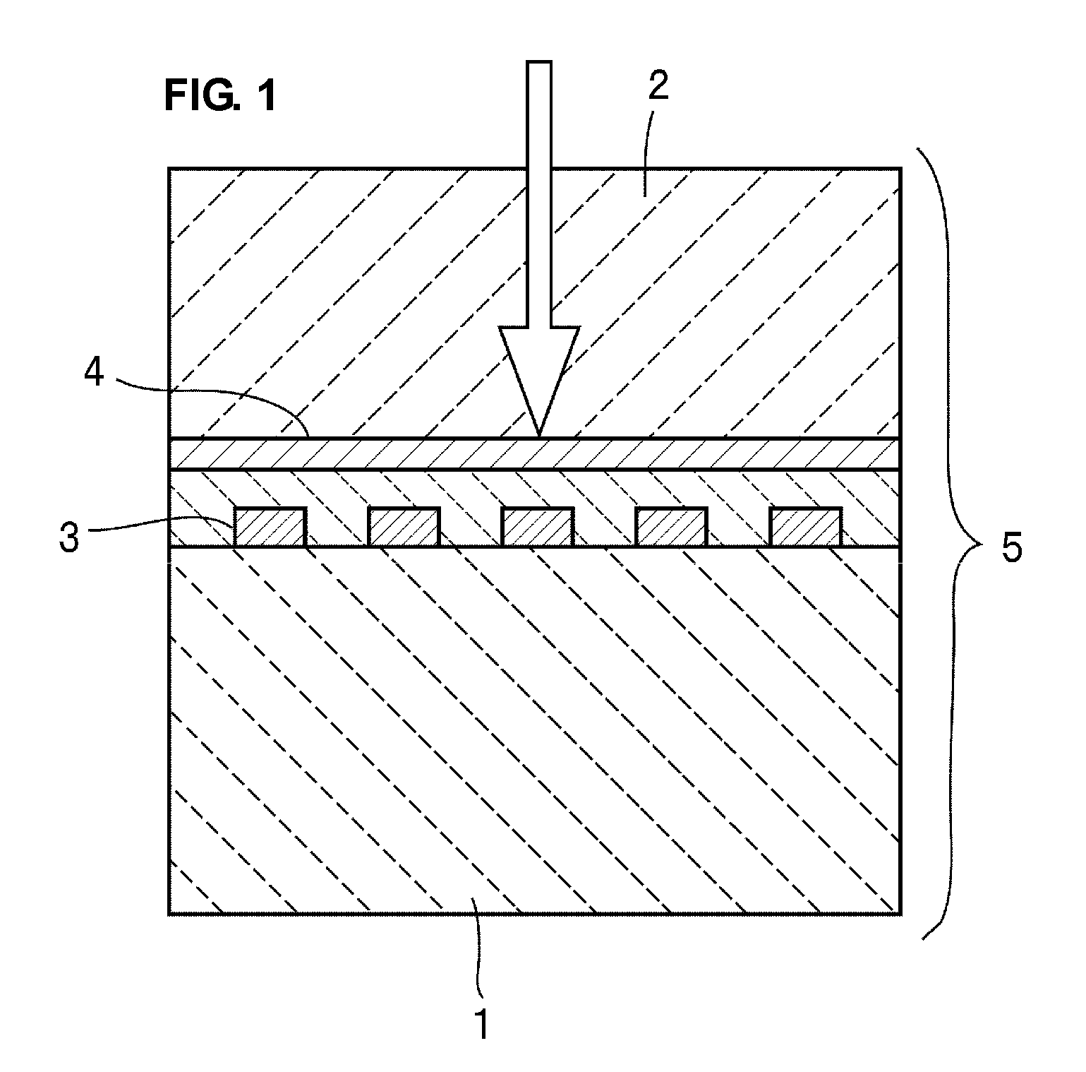
[0043]FIG. 1 is a front cross-sectional view that schematically illustrates a method for manufacturing a boundary acoustic wave device according to one preferred embodiment of the present invention.

[0044]According to the manufacturing method in the present preferred embodiment, a laminated structure 5 illustrated in FIG. 1 is first prepared. In the laminated structure 5, a second medium 2 preferably made of silicon dioxide (SiO2) is laminated on a first medium 1 preferably made of lithium niobate (LiNbO3). An interdigital transducer (IDT) electrode 3 is arranged between the first medium 1 and the second medium 2. The IDT electrode 3 is preferably made of gold.

[0045]A reform medium layer 4 is disposed in the second medium 2. When being subjected to laser beam irradiation, the reform medium layer 4 is reformed. In the present prefer...


PUM

PropertyMeasurementUnit
thicknessaaaaaaaaaa
thicknessaaaaaaaaaa
thicknessaaaaaaaaaa

Abstract

A method for manufacturing a boundary acoustic wave device includes the steps of preparing a laminated structure in which an IDT electrode is disposed at an interface between first and second solid media and reforming the first medium and / or the second medium by externally providing the laminated structure with energy capable of reaching the inside of the first medium and / or the second medium and thus adjusting a frequency of the boundary acoustic wave device. The above provides a boundary acoustic wave device manufacturing method that enables frequency adjustment to be readily performed with high accuracy.

Description

BACKGROUND OF THE INVENTION[0001]1. Field of the Invention[0002]The present invention relates to a method for manufacturing a boundary acoustic wave device utilizing a boundary acoustic wave propagating through an interface between first and second solid media and relates to a boundary acoustic wave device. More specifically, the present invention relates to a boundary acoustic wave device manufacturing method including a step of adjusting frequency characteristics and relates to a boundary acoustic wave device.[0003]2. Description of the Related Art[0004]A surface acoustic wave device is widely used as a band-pass filter or a resonator, for example, in a cellular phone. In a surface acoustic wave device, an interdigital transducer (IDT) electrode is disposed on a piezoelectric substrate, and the IDT electrode receives and excites a surface acoustic wave. Accordingly, in order to avoid interference with reception and excitation of a surface acoustic wave, it is necessary to have a s...

Claims


Application Information

Patent Timeline
Patent Type & Authority Applications(United States)
IPC IPC(8): H01L41/04H01L41/22H03H3/10H10N30/80H03H9/145H10N30/87
CPCH03H3/08H03H9/0222Y10T29/4908Y10T29/42Y10T29/49005Y10T29/49007
Inventor KANDO, HAJIMEMIMURA, MASAKAZU
Owner MURATA MFG CO LTD
Learn More