Mobility tracking method and user location tracking device

a mobile terminal and location tracking technology, applied in the field of mobile terminal location tracking, can solve the problems of difficult to measure a relative location with respect to the reference point, and cannot be used as a reference point for range-based localization,

Inactive Publication Date: 2009-08-13
PANASONIC CORP
View PDF7 Cites 113 Cited by
  • Summary
  • Abstract
  • Description
  • Claims
  • Application Information

AI Technical Summary

Benefits of technology

[0014]The present invention is conceived in view of the stated problems, and an object of the present invention is to provide a mobility tracking method and a user location tracking device which can track where the user is at all times by estimating a topology of a travel path taken by the user who only carries a small-sized terminal, without using location information such as GPS coordinates.
[0021]To be more specific, in the case where the period of time during which the tracking object is moving along the tracked path is known, the end time is the deviation time whereas the start time is the return time. Especially, when the tracking object is moving along the same path that has been taken before, an area with a high degree of similarity appears as a sloped line in the triangular matrix, so that the deviation time and the return time can be easily determined according to pattern recognition.
[0029]Also, in order to avoid accumulation of environmental changes over time, the estimating of the topology may further include retraining to update the observation probability of the hidden Markov model using the historical data obtained from the return time to the deviation time.
[0044]With this, when a family member or a friend who owns the user location tracking device comes within a distance taking a fixed travel period of time, the distance can be notified in an actual travel period of time. It should be noted that according to the conventional technology using a GPS, a method of notifying a distance in a straight line between GPS coordinates is considered. In this case, there is a possibility that the user has to take a long way around in reality even when the notified distance is short. Here, when combined with map information, a distance measured along the road can be estimated. However, when the path has not been taken before, it may take time to move while looking at a map. Meanwhile, according to the present invention, when a child or an elderly person who owns the user location tracking device asks another user who owns another user location tracking device for help, the time actually taken for this other user to go to the place which has been visited before by the other user is notified and this is particularly useful.

Problems solved by technology

Using the conventional range-based localization described above, although radio waves from a great number of access points of wireless LANs can be received outdoors by virtue of the proliferation of wireless LANs at home, the coordinates of these access points are unknown in general and thus cannot be used as reference points for the range-based localization.
Also, in a non-line-of-sight environment where an obstruction exists between a reference point and a mobile terminal or in a multipath environment, it is difficult to measure a relative location with respect to the reference point.
For this reason, even when the coordinates of the access points in homes can be acquired, it is still hard to determine the location of the outdoor mobile terminal.
However, the wireless devices whose coordinates are unknown cannot be used as reference points.
Furthermore, when the conventional fingerprinting-based localization is used, the coordinates of the reference points are unnecessary and the method is suitable for the non-line-of-sight environment and the multipath environment.
Thus, it is difficult to employ this method outdoors in a wider region.

Method used


Image

  • Mobility tracking method and user location tracking device
  • Mobility tracking method and user location tracking device
  • Mobility tracking method and user location tracking device

Examples


first embodiment

[0081]The following is a description of a mobility tracking method according to the first embodiment of the present invention, with reference to the drawings.

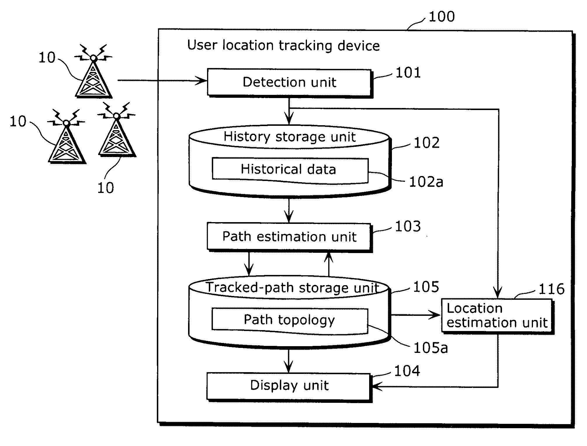
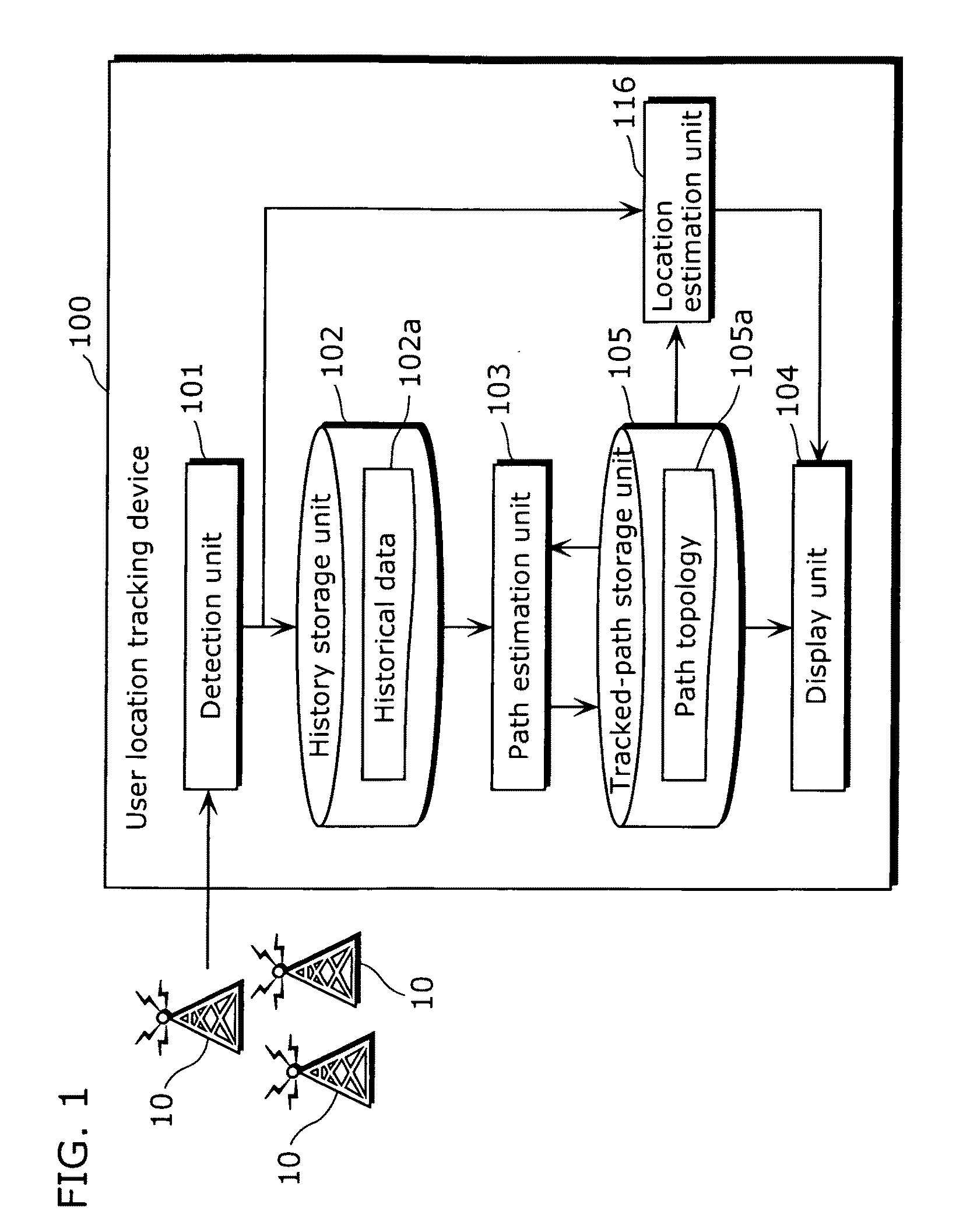
[0082]FIG. 1 is a block diagram showing a configuration of a user location tracking device 100 which realizes the mobility tracking method, according to the first embodiment of the present invention.

[0083]Using IEEE 802.11 access points which are ubiquitously available, the user location tracking device 100 tracks the location of a user who owns the user location tracking device 100. As shown in FIG. 1, the user location tracking device 100 includes a detection unit 101, a history storage unit 102, a path estimation unit 103, a tracked-path storage unit 105, a location estimation unit 116, and a display unit 104.

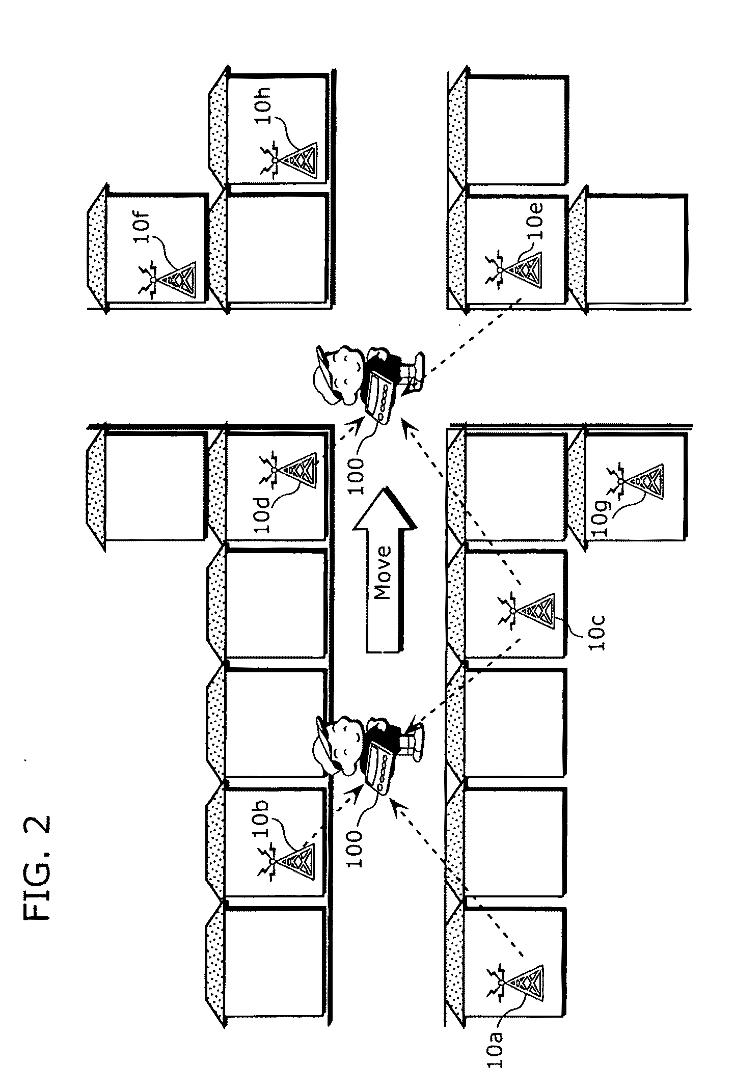
[0084]At a position where the user location tracking device 100, which is a tracking object, is situated, the detection unit 101 receives radio waves sent from ubiquitously available wireless devices 10 and detects whic...

second embodiment

[0121]In the present embodiment, a hidden Markov model (HMM) is used by the path estimation unit 103 for pattern recognition and tracked-path holding. The Tanimoto coefficient is calculated based on the parameters of the observation probability of the hidden Markov model. On account of this, when the same path is traveled over and over again, the amount of calculation can be reduced as compared to the case where the calculation is performed among the historical data sets. It should be noted that components which are not particularly explained in the present embodiment are the same as those shown in FIG. 1.

[0122]More specifically, the tracked path is held as a hidden Markov model in which the location of the user location tracking device 100 is a state variable and the wireless device information detected by the detection unit 101 is an observed variable.

[0123]From the historical data and the hidden Markov models of the tracked paths obtained up to the current time, the deviation jud...

first modification

(First Modification)

[0181]In the above second embodiment, the user location tracking device 100 does not estimate its current location. On the other hand, in the present modification, the user location tracking device 100 estimates its current location using the location estimation unit 116. To be more specific, when the user location tracking device 100 is not deviating from the tracked path, the location estimation unit 116 performs maximum likelihood estimation for estimating the current location of the user location tracking device 100, using the historical data and the hidden Markov models obtained up to the current time.

[0182]FIG. 18 is a flowchart showing processing performed by the path estimation unit 103, according to the first modification of the second embodiment. Note that an explanation regarding the same steps as in the flowchart of FIG. 12, that is, steps S202 to S206 and steps S208 to S220, is omitted here and that only a different step, i.e., step S222, is explaine...


PUM


Abstract

A user location tracking method allows a topology of a travel path taken by a user to be estimated without the use of location information such as GPS coordinates, so that a travel range of the user who only carries a small-sized terminal can be tracked at all times. The mobility tracking method is employed by a user location tracking device which uses radio waves sent from wireless devices distributed ubiquitously, the mobility tracking method including: detecting wireless device information identifying wireless devices out of the ubiquitously available wireless devices when the radio waves are received at a location where the user location tracking device is situated; storing the detected wireless device information as historical data; and estimating a topology, as the user location tracking device is moving, that shows a positional relation and a connection relation of a travel path taken by the user location tracking device, the estimation being performed on the basis that the location of the user location tracking device has deviated from a previously tracked path which has been traveled before by the user location tracking device and that the location of the user location tracking device has returned to the previously tracked path, using the stored historical data.

Description

BACKGROUND OF THE INVENTION[0001](1) Field of the Invention[0002]The present invention relates to a mobility tracking method and a user location tracking device used for tracking where a user is using radio waves from ubiquitously available wireless devices and, more characteristically, to a mobility tracking method and a user location tracking device used for tracking a travel range of the user through location estimation carried out using an unsupervised training algorithm based on time series data.[0003](2) Description of the Related Art[0004]In recent years, many crimes against small children, including elementary school students, have been occurring, which has become a social problem. For the safety of children, it is important to guide the children not to go to dangerous places. In that sense, it is said to be necessary for a parent to know where his or her child is. Also, there is a need for enhanced service, such as offers of health advice and provision of information suited...

Claims


Application Information

Patent Timeline
Patent Type & Authority Applications(United States)
IPC IPC(8): G08B1/08G01S5/02H04W4/02H04W64/00H04W84/12
CPCG01S5/0294G01C21/20
Inventor KAJI, MITSURU
Owner PANASONIC CORP
Why Eureka
Try Eureka