Spin-torque oscillator, magnetic head including the spin-torque oscillator, and magnetic recording and reproducing apparatus

a spin-torque oscillator and spin-torque technology, which is applied in special recording techniques, magnetic bodies, instruments, etc., can solve the problems of small oscillation output power p, disadvantage of gmr oscillation devices, and inability to use in practical use, etc., and achieve high output and high q value

Active Publication Date: 2009-08-13
KK TOSHIBA
View PDF11 Cites 83 Cited by
  • Summary
  • Abstract
  • Description
  • Claims
  • Application Information

AI Technical Summary

Benefits of technology

[0016]The present invention has been made in view of these circumstances, and an object thereof is to provide a spin-torque oscillator that has a high Q valu

Problems solved by technology

The high Q value is an advantage of a GMR oscillation device, but small oscillation output power P is a disadvantage of the GMR oscillation device.
An output from a single GMR oscillation device is a very small amount of power of the order of nanowatts, which is far from a practical power level of microwatts, and is not suitable for practical use.
This seems to lead to difficulties in device manufacture.
In a spin-torque oscillator having a magnetic tunnel junction film such as a MgO-TMR film, however, a current with high current density cannot be

Method used


Image

  • Spin-torque oscillator, magnetic head including the spin-torque oscillator, and magnetic recording and reproducing apparatus
  • Spin-torque oscillator, magnetic head including the spin-torque oscillator, and magnetic recording and reproducing apparatus
  • Spin-torque oscillator, magnetic head including the spin-torque oscillator, and magnetic recording and reproducing apparatus

Examples


first embodiment

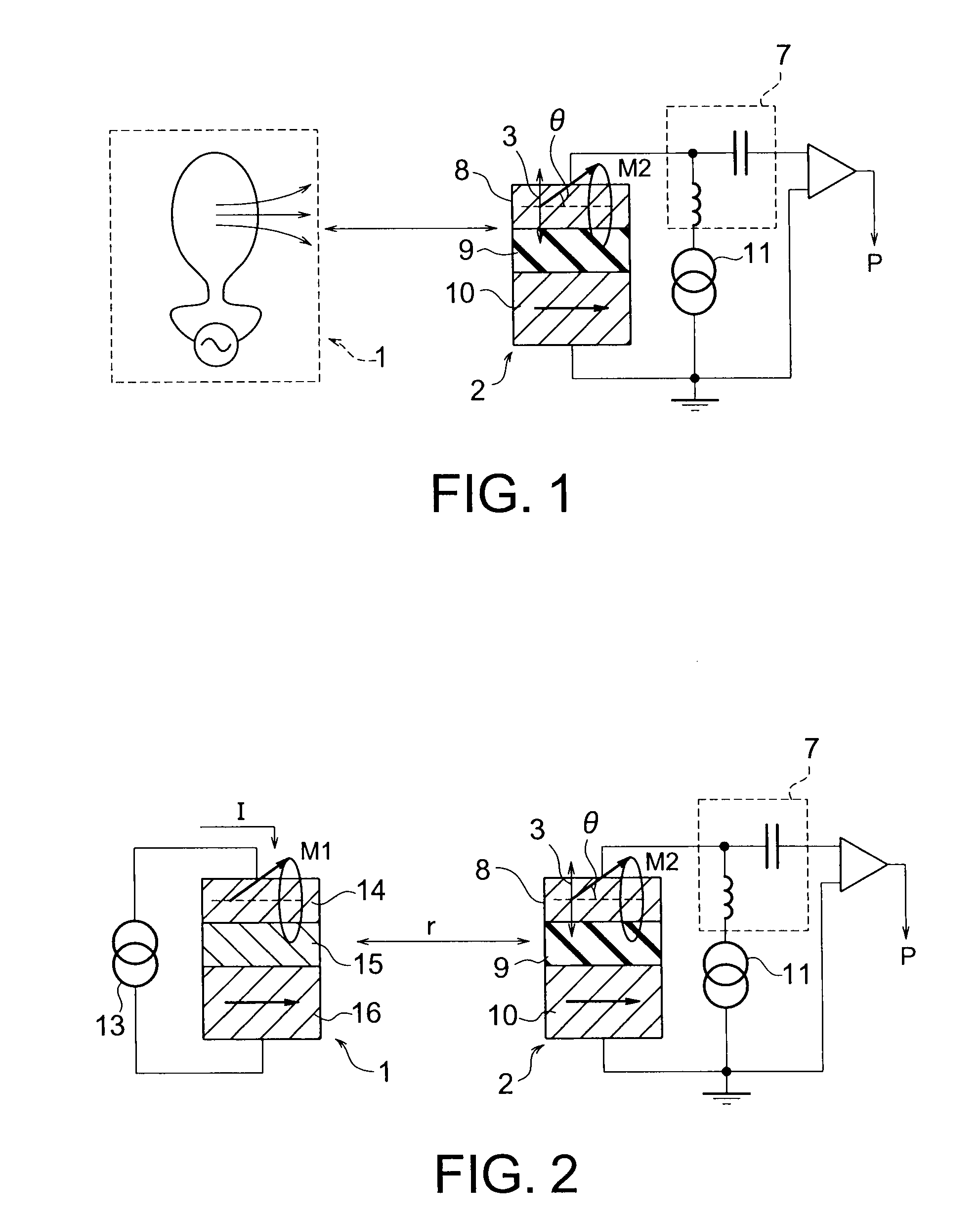
[0031]FIG. 1 illustrates a spin-torque oscillator in accordance with a first embodiment of the present invention. The hybrid spin-torque oscillator it accordance with the first embodiment includes an oscillating field generating unit 1 and a magnetoresistive element unit 2 that has a ferromagnetic multi-layer film. The oscillating field generating unit 1 and the magnetoresistive element unit 2 are magnetostatically coupled to each other. The spin-torque oscillator may include more than one oscillating field generating unit 1. The oscillating field generating unit 1 may be any type of magnetic device such as a coil having an AC source or a conventional spin-torque oscillator, as long as the device can generate an oscillating field.

[0032]The magnetoresistive element unit 2 has a three-layer structure as a fundamental structure that is formed with a magnetization free layer 8, a spacer layer 9, and a magnetization pinned layer 10. The magnetization free layer 8 has a magnetization of w...

second embodiment

[0039]FIG. 2 illustrates a spin-torque oscillator in accordance with a second embodiment of the present invention. The spin-torque oscillator in accordance with this embodiment is the same as the spin-torque oscillator of the first embodiment shown in FIG. 1, except that the oscillating field generating unit 1 is a CPP-GMR device that has a three-layer structure formed with a magnetization free layer 14, a spacer layer 15, and a magnetization pinned layer 16. The current I to be supplied by a power supply 13 is large enough to oscillate the magnetization M1 in the magnetization free layer 14, using a spin transfer effect. Therefore, the oscillating field generating unit 1 has a similar structure to a conventional GMR oscillation device. The oscillating field 3 generated from the oscillating field generating unit 1 is an oscillating dipole field formed by the oscillation of the magnetization M1 of the magnetization free layer 14. The oscillating dipole field formed by the magnetizati...

third embodiment

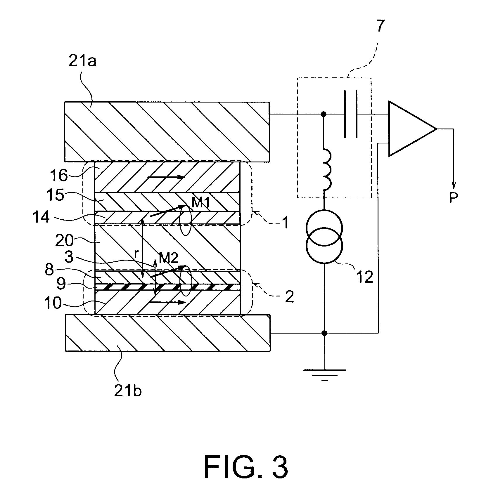
[0044]Referring again to FIG. 2, a spin-torque oscillator in accordance with a third embodiment of the present invention is described. The spin-torque oscillator in accordance with this embodiment is the same as the spin-torque oscillator of the second embodiment, except that the magnetoresistive element unit 2 is formed with a magnetic tunnel junction (MTJ) device.

[0045]In a conventional TMR oscillation device, a large amount of current cannot be supplied, so as to avoid the problem of a dielectric breakdown. As a result, only an unstable oscillation (a low Q value) is obtained as the oscillation of the magnetization M2 of the magnetization free layer 8.

[0046]In the spin-torque oscillator of this embodiment, on the other hand, the oscillation of the magnetization M2 of the magnetization free layer 8 is caused by the oscillating field generated from the oscillating field generating unit 1. Accordingly, a large amount of current is not required to obtain a high Q value. To achieve an...


PUM


Abstract

It is made possible to to provide a spin-torque oscillator that has a high Q value and a high output. A spin-torque oscillator includes: an oscillating field generating unit configured to generate an oscillating field; and a magnetoresistive element including a magnetoresistive effect film including a first magnetization pinned layer of which a magnetization direction is pinned, a first magnetization free layer of which a magnetization direction oscillates with the oscillating field, and a first spacer layer interposed between the first magnetization pinned layer and the first magnetization free layer.

Description

CROSS-REFERENCE TO RELATED APPLICATION[0001]This application is based upon and claims the benefit of priority from prior Japanese Patent Application No. 2008-31789 filed on Feb. 13, 2008 in Japan, the entire contents of which are incorporated herein by reference.BACKGROUND OF THE INVENTION[0002]1. Field of the Invention[0003]The present invention relates to a spin-torque oscillator, a magnetic head including the spin-torque oscillator, and a magnetic recording and reproducing apparatus.[0004]2. Related Art[0005]It is known that a steady-state microwave signal that responses to a direct current can be generated by taking advantage of the spin transfer effect caused in a nano-scale magnetic multi-layer film having a spacer layer interposed between magnetic layers (see “Microwave oscillations of a nanomagnet driven by a spin-polarized current”, S. I. Kiselev, et al., Nature 425, 380 (2003), for example). The origin of the microwave signal is an magnetization oscillation in a magnetizat...

Claims


Application Information

Patent Timeline
IPC IPC(8): G11B5/33
CPCB82Y25/00G01R33/093G01R33/1284G11B5/02G11B5/3903G11B2005/0002Y10T428/1143H01F10/3254H01L43/08H03B15/006Y10T428/1114Y10T428/1121H01F10/325H10N50/10G01R33/20G11B5/33H10N50/00
Inventor KUDO, KIWAMUNAGASAWA, TAZUMIMIZUSHIMA, KOICHISATO, RIE
Owner KK TOSHIBA
Why Eureka
Try Eureka