
Dryer and adapter having ducting system

a ducting system and adapter technology, applied in the field of dryers, can solve the problems of unpleasant and harmful air in high temperature and high moisture content of air within the house or building, and harmful effects on the house or building of the dryer, so as to reduce energy consumption and improve drying efficiency.

Inactive Publication Date: 2009-08-20
PROTEGE ENTERPRISES
View PDF98 Cites 13 Cited by
  • Summary
  • Abstract
  • Description
  • Claims
  • Application Information

AI Technical Summary

Benefits of technology

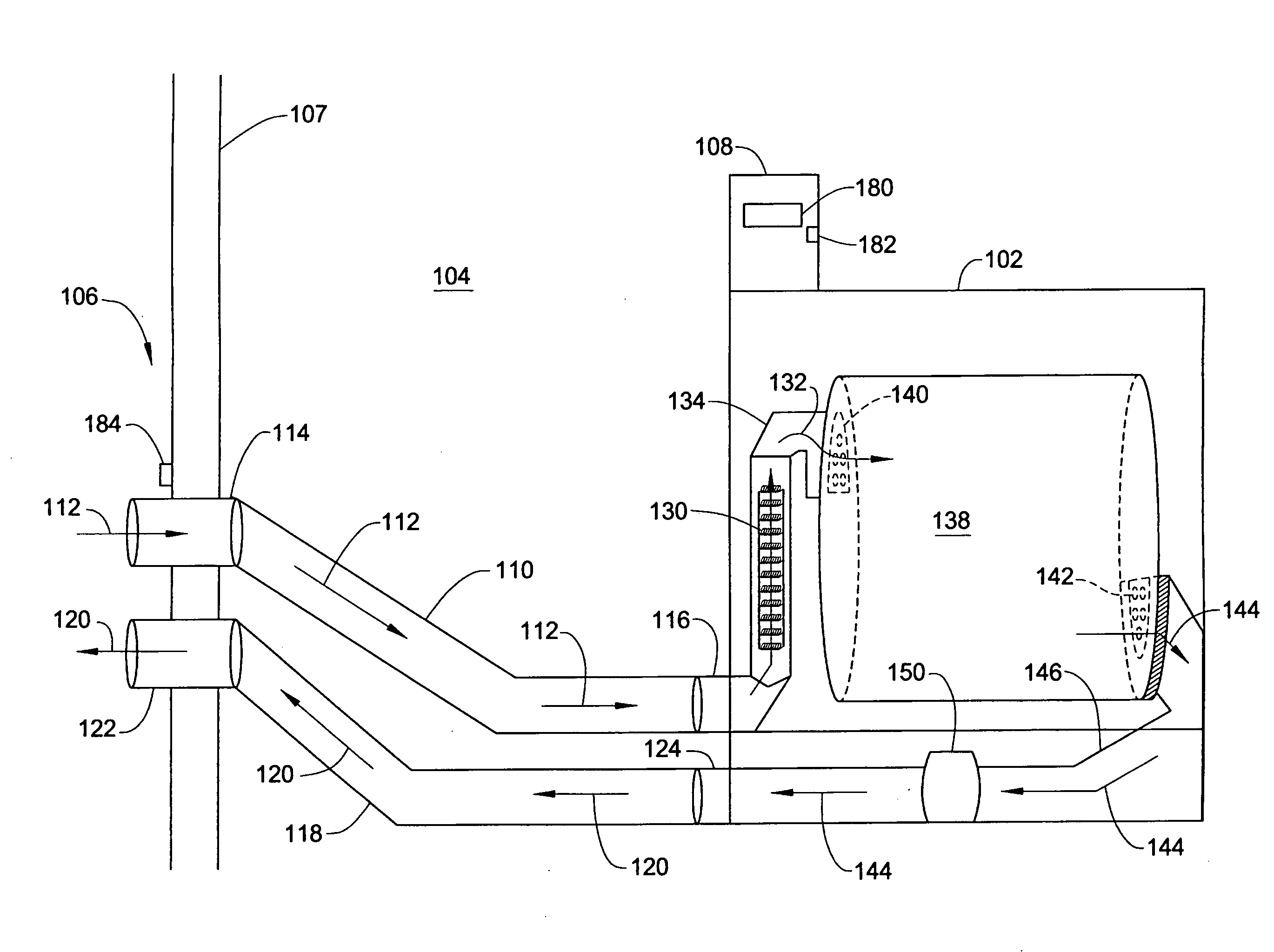
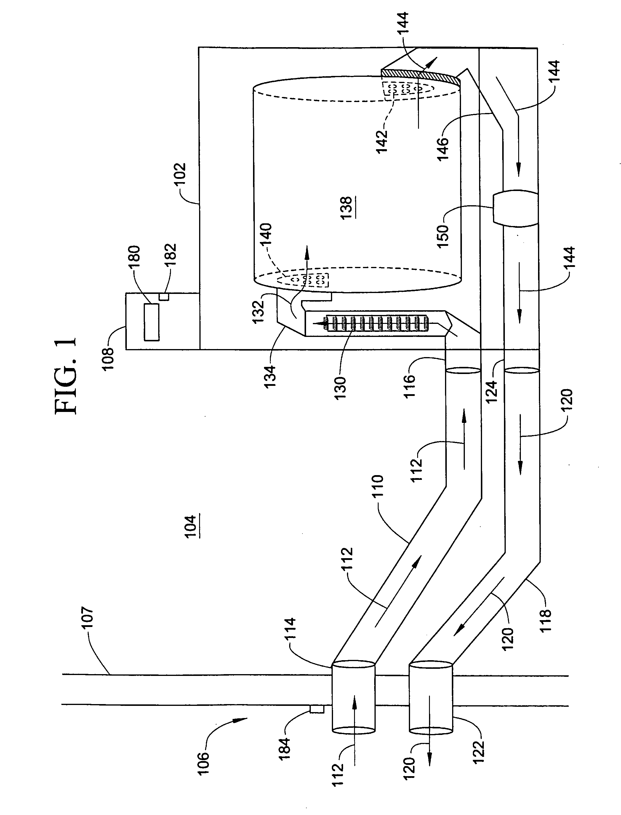
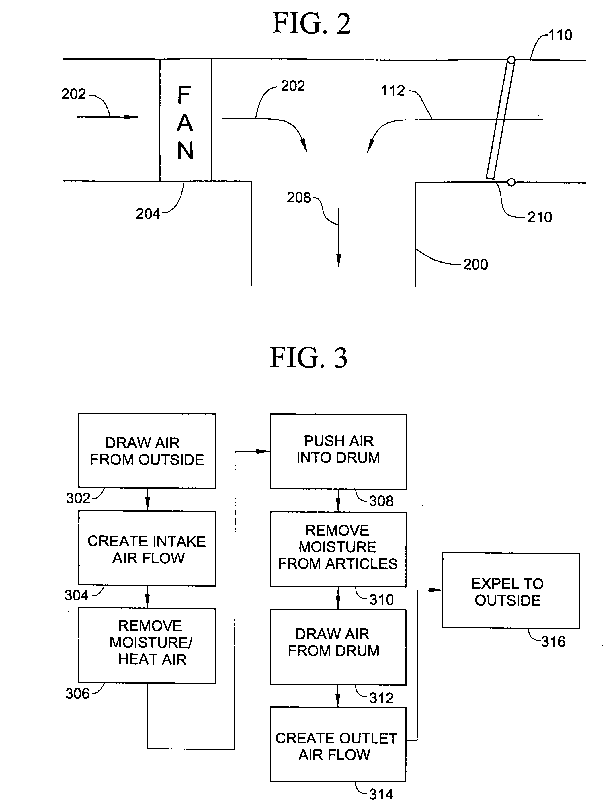
The present invention is a dryer adapter and apparatus that improves drying efficiency and reduces energy consumption. It includes two vents that eliminate negative pressure on the building caused by dryer use. The adapter exchanges air with the outside, allowing the dryer to select between inside air or outside air based on the vapor pressure of the different air locations. The invention reduces vapor pressure in air resulting from drying, which in turn reduces the amount of energy needed to evaporate the air. The method involves drawing air from outside the room or structure to create an intake air flow path, heating the air to remove moisture from articles within the dryer, and expelling the heated air through an outlet air duct to outside the room or structure. Overall, the invention saves energy, reduces costs, and conserves resources.

Problems solved by technology

Failure to blow the heated air outside results in air within the house or building having a high temperature and high moisture content.
Air having these characteristics would be unpleasant and harmful.
Even if the exhaust air blows outside, harmful effects occur on the house or building of the dryer.
This process results in extra energy costs to owners or users of the house.
In a commercial laundry setting, these costs can be substantial.
Thus, the dryer, when on, increases energy consumption, wastes resources and drives up costs.

Method used


Image

  • Dryer and adapter having ducting system
  • Dryer and adapter having ducting system
  • Dryer and adapter having ducting system

Examples


Embodiment Construction

[0018]Aspects of the invention are disclosed in the accompanying description. Alternate embodiments of the present invention and their equivalents are devised without parting from the spirit or scope of the present invention. It should be noted that like elements disclosed below are indicated by like reference numbers in the drawings.

[0019]FIG. 1 depicts a dryer 102 having an intake duct 110 and an outlet duct 118 according to the disclosed embodiments. Dryer 102 may use forced, heated air to remove moisture and wetness from articles, such as clothes, towels, fabric, dishes, household items, and the like. Preferably, the articles are contained within a rotating drum housed in dryer 102. The forced air passes over the articles to remove moisture from them. Dryer 102 comprises the components of dryers known in the art, which are not disclosed in great detail here. Essentially, dryer 102 is any dryer that uses heated air to dry articles, such as clothes.

[0020]Dryer 102, however, differ...


PUM


Abstract

An adapter to a dryer, or a new configuration to a dryer, allows articles, such as clothes, towels, sheets and the like to dry with reduced energy consumption. The adapted configuration draws air from outside the room or structure housing the dryer. The outside air is then used to dry the articles. The outside air can be heated within the dryer using the existing heater prior to entering the drum holding the articles. After the heated air removes moisture from the articles, the moist, hot air is expelled outside the room or structure through an outlet air duct. Thus, air within the room or structure is not used for the drying process and conditions such as temperature and pressure are not changed when the dryer is on.

Description

BACKGROUND OF THE INVENTION[0001]The present invention relates to a dryer using heated air to dry items. More particularly, the present invention relates to a dryer using a ducting system to select air from outside a room or structure that enhances a drying process.DISCUSSION OF THE RELATED ART[0002]Clothes dryers basically work in the same manner. The dryer sucks in air from the surrounding area. The dryer heats the air using an electric heating element, a gas burner and the like. The air passes into a tumbler housed within the dryer once it is heated. The hot air evaporates water from the clothes as they spin inside the tumbler. The dryer then forces the evaporated water out along with the hot air. Typically, a vent allows the air and moisture to exit the room.[0003]As noted above, the dryer draws air from the surrounding area, such as a basement or laundry room. The dryer heats this air and blows it across wet clothes, towels, and the like. Typically, the blown air includes a hig...

Claims


Application Information

Patent Timeline
Patent Type & Authority Applications(United States)
IPC IPC(8): F26B21/04D06F58/48
CPCD06F58/20D06F58/02D06F58/48D06F2103/30D06F2103/32Y02B40/00
Inventor DEWALD, III, CHARLES ROBERTCRISTELLO, THOMAS L.
Owner PROTEGE ENTERPRISES
Learn More