Fuel injector with real-time feedback control

a fuel injector and real-time feedback technology, applied in the direction of machines/engines, transportation and packaging, liquid transfer devices, etc., can solve the problems of poor combustion and emission, difficult to directly measure the fueling flow rate, and deterioration of the air-fuel ratio control, etc., to facilitate the control of the shape of the fuel injection puls

Inactive Publication Date: 2009-08-20
YAN MI
View PDF3 Cites 27 Cited by
  • Summary
  • Abstract
  • Description
  • Claims
  • Application Information

AI Technical Summary

Benefits of technology

[0022]In addition to real-time feedback control for fueling rate, the piston device also facilitates controlling the shape of fuel injection pulses. In another embodiment of the present invention, an actuator module which includes an actuator and a position sensor is positioned in between the spring constraint and

Problems solved by technology

Due to the high pressure high temperature working environment in fuel injectors, it is hard to measure the fueling flow rate directly.
Control error and injector deterioration may cause poor combustion and emission issues.
Performance change in fueling rate control, especially that caused by fuel system deterioration is a perturbation to the control system rather than a disturbance, causing deterioration in air-fuel ratio control.
Fuel injector deterioration in some cylinders may cause over or under fueling in other cylinders, resulting in fuel economy, torque balance, and emission issues.
In common-rail systems, fuel pressure is kept constant,

Method used


Image

  • Fuel injector with real-time feedback control
  • Fuel injector with real-time feedback control
  • Fuel injector with real-time feedback control

Examples


Embodiment Construction

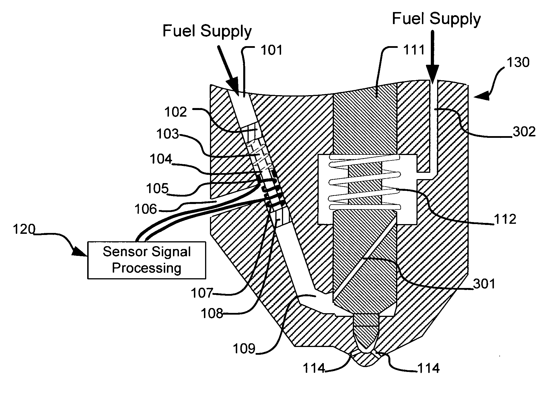
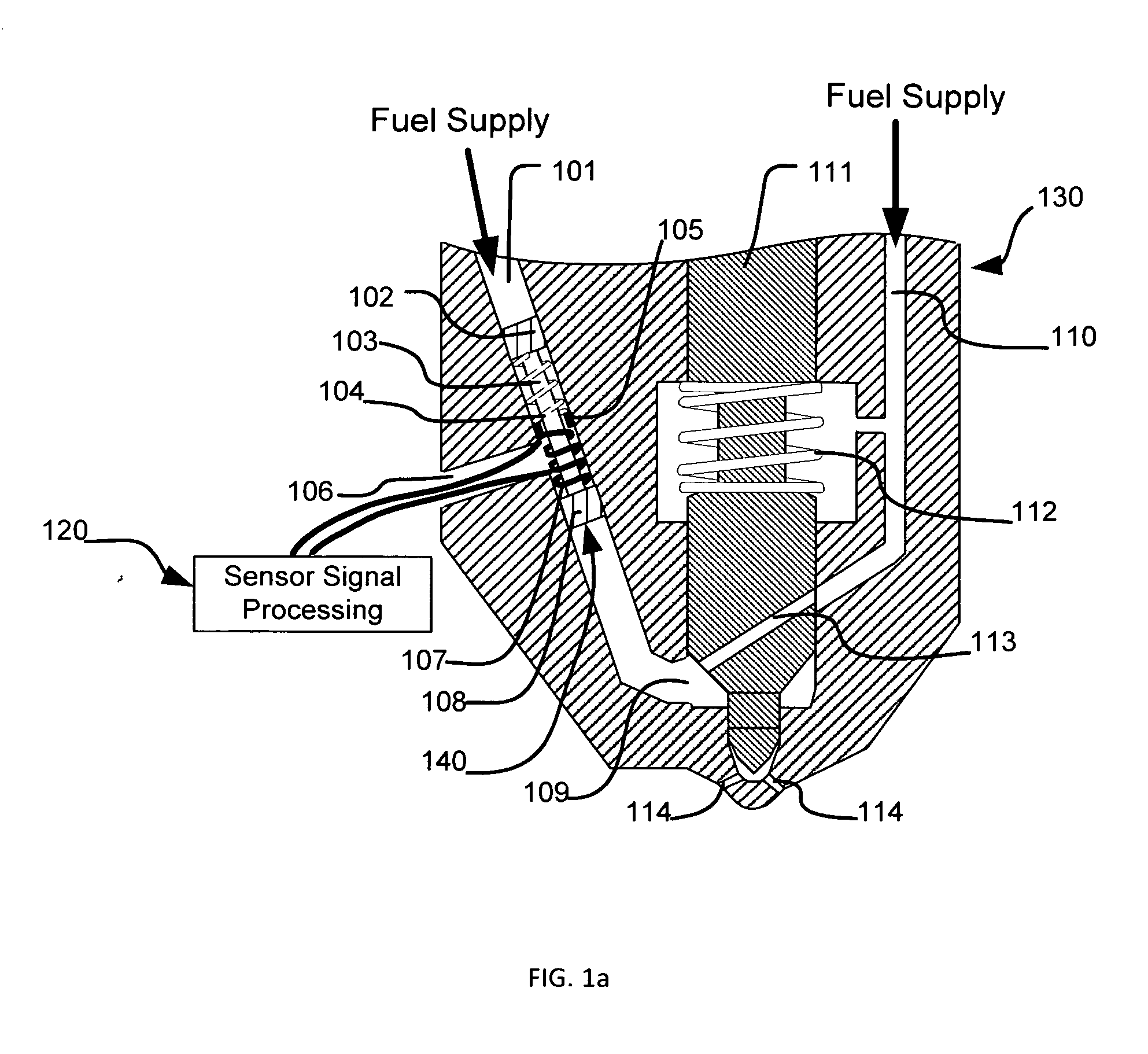
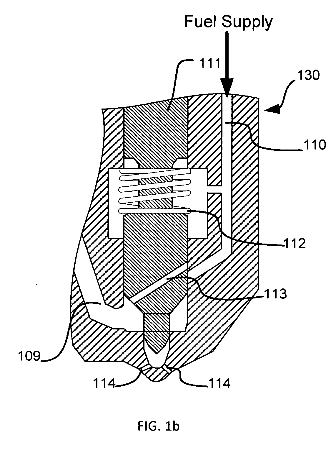
[0034]Referring to FIG. 1a, an injector 130 includes a needle valve 111, which controls fuel flow. When the needle valve leaves its seat, a spring 112 is pressed and a cavity 109 inside the injector 130 connects to combustion chamber (not shown) through injector orifices 114 allowing high pressure fuel in the cavity being spayed out. After an injection completes, the valve needle returns to its seats under the stress provided by the spring 112, blocking fuel from entering combustion chamber. Inside the needle valve 111, a conduit 113 connects a conduit 110 in the injector body to the cavity 109 when the needle valve is in its seat. The cavity 109 also connects to a channel 101, in which a piston 140 separates the fuel inside the cavity 109 from a high pressure fuel supply. The piston 140 includes a return spring 104, an upper head 102, a lower head 108, and a connecting rod 103 between the upper and lower heads. The spring 104 is positioned between the upper head 102 and a spring re...


PUM


Abstract

A fuel injection apparatus with a piston device that includes a channel and a piston in the channel. A position sensor is used to detect the piston movement inside the channel when the fuel injection apparatus is energized and de-energized, and the sensing value is used for controlling fuel injection rate in real-time and diagnosing failures in the apparatus. With an actuator installed, the piston can also be used for independently modulating fuel pressure during fuel injection. Thereby the shape of fuel injection pulses is controlled. The fuel injection apparatus has three injection states, and flexible fuel injection timing and multi-pulse injection are allowed. Furthermore, in all injection states, fuel supply has no direct contact to combustion chamber. As a result, when a malfunction sticks the apparatus open, no fuel is supplied. This feature provides a safety nature to the fuel injection apparatus.

Description

[0001]This present application claims priority from U.S. provisional application No. 61 / 065,840 having the same title as the present invention and filed on Jul. 17, 2007.CROSS-REFERENCE TO RELATED APPLICATIONS[0002]Not ApplicableSTATEMENT REGARDING FEDERALLY SPONSORED RESEARCH OR DEVELOPMENT[0003]Not ApplicableREFERENCE TO SEQUENCE LISTING, A TABLE, OR A COMPUTER PROGRAM LISTING COMPACT DISC APPENDIX[0004]Not ApplicableFIELD OF THE INVENTION[0005]The present invention relates to a fuel injection apparatus that provides and controls fuel flow.BACKGROUND OF THE INVENTION[0006]Fuel injectors are used to direct fuel into a combustion chamber. Normally inside a fuel injector, fuel is pressurized, and a nozzle assembly including a nozzle valve (nozzle needle valve) is used to control fuel flow through nozzle orifices. At “off” position, the nozzle valve blocks fuel flow. When the nozzle valve moves to “on” position, fuel is injected through the orifices. The overall fueling rate is contro...

Claims


Application Information

Patent Timeline
IPC IPC(8): B05B1/30
CPCF02M47/027F02M2200/24F02M61/1873
Inventor YAN, MI
Owner YAN MI
Why Eureka
Try Eureka