Solid-state switch capable of bidirectional operation

a solid-state switch and bi-directional technology, applied in the field of solid-state switching devices, can solve the problems of not being able to be turned off at a controllable point in an ac cycle, being unnecessarily bulky and complex in construction, and being high in on-state voltage and resistance, and achieves greater versatility and utility.

Active Publication Date: 2009-08-20
SANKEN ELECTRIC CO LTD
View PDF3 Cites 55 Cited by
  • Summary
  • Abstract
  • Description
  • Claims
  • Application Information

AI Technical Summary

Benefits of technology

[0009]The present invention has it as an object to impart greater versatility and utility to a monolithic, solid-state switching device of symmetrical design than heretofore.

Problems solved by technology

The TRIAC has the weakness that, once triggered, it remains conductive until the current flowing therethrough drops below a predefined threshold value.
It cannot possibly be turned off at a controllable point in an AC cycle.
These prior art bidirectional switching circuits, all incorporating discrete normally-off electronic switches, are alike in being unnecessarily bulky and complex in construction and high in on-state voltage and resistance.
Moreover, being made from semiconducting silicon materials with relatively low bandgaps, such known devices are not so high in antivoltage strength as can be desired.
Offsetting these benefits, however, is the fact that the device is materially less versatile in use than the multifunction bidirectional switch first cited above, the former being incapable of operation in two of the four different modes possible with the latter.
This solution is impossible, or at least undesirable, in electronic switches of symmetrical design now under consideration, in which each of the two ohmic electrodes may serve as either source or drain.

Method used


Image

  • Solid-state switch capable of bidirectional operation
  • Solid-state switch capable of bidirectional operation
  • Solid-state switch capable of bidirectional operation

Examples


embodiment

of FIG. 7

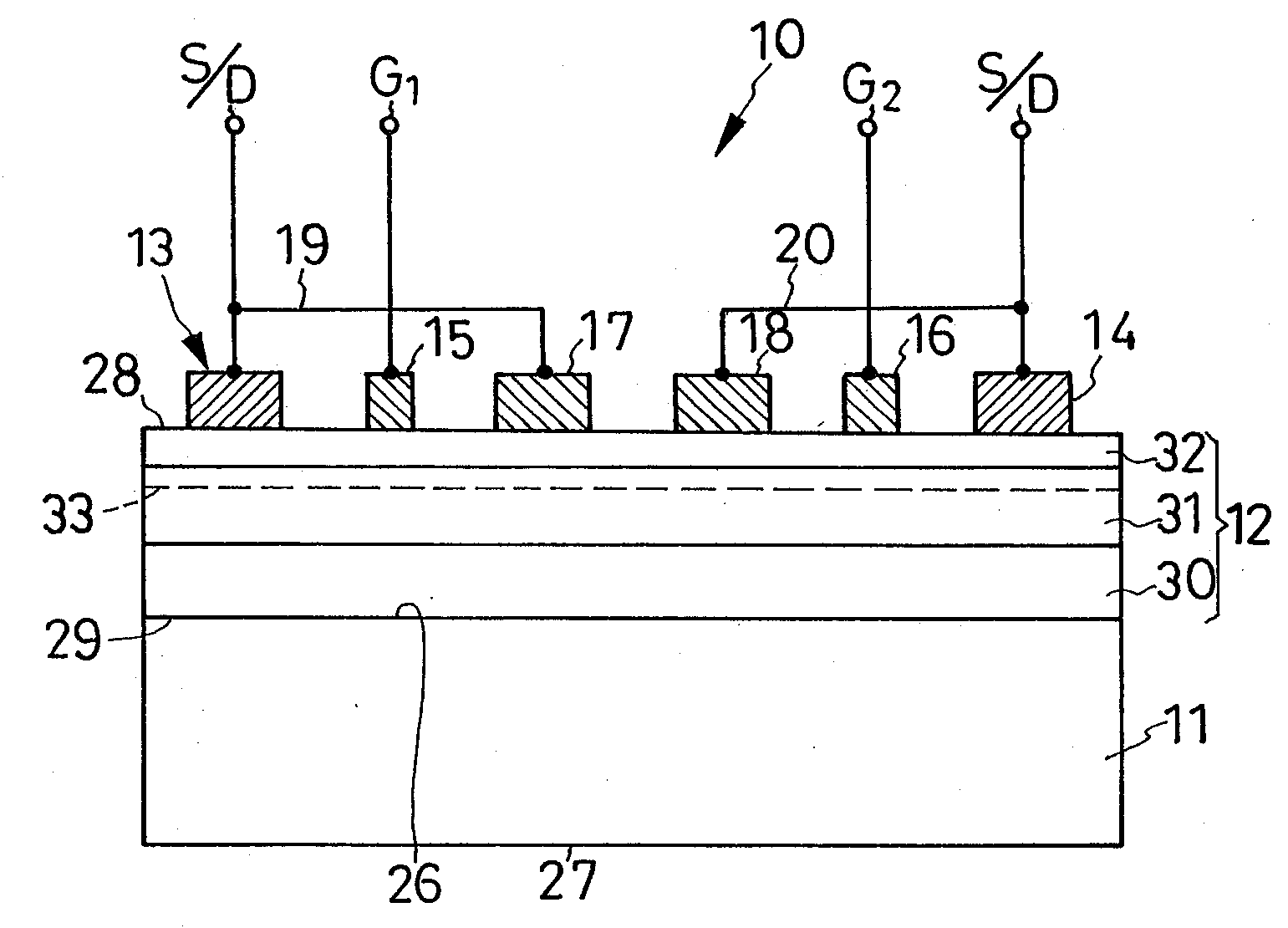
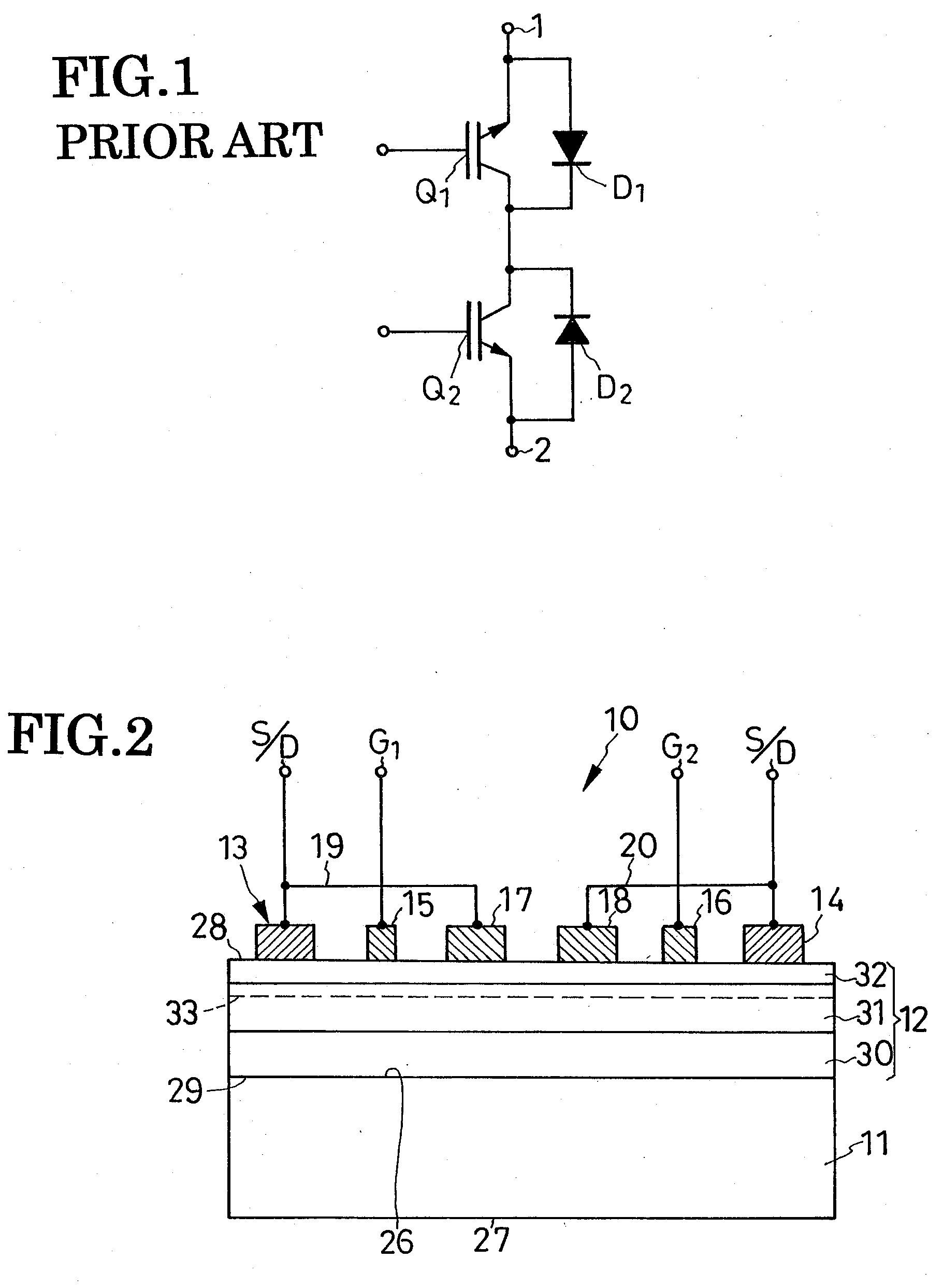
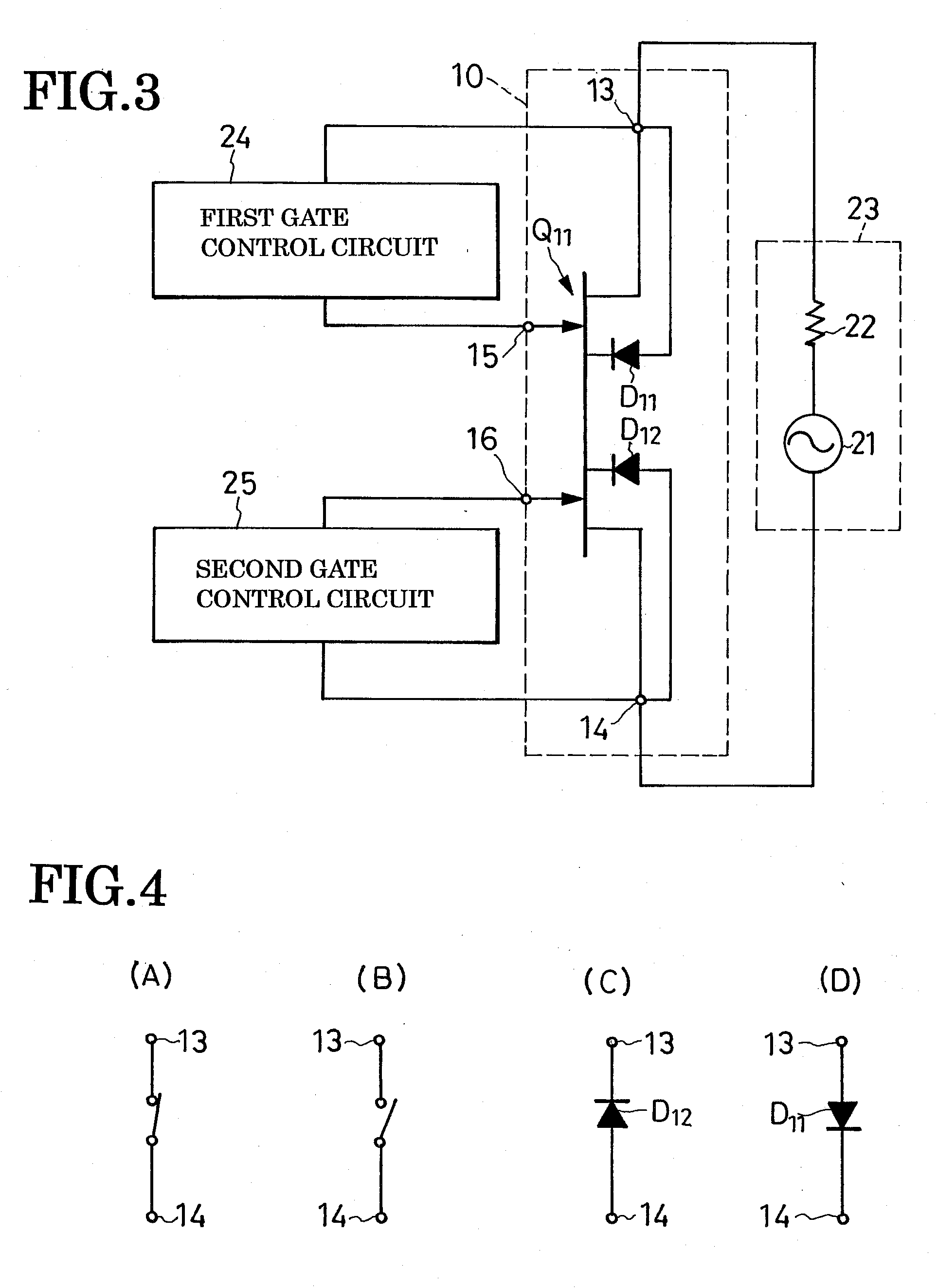
[0099]Unlike the switching device 10a, FIG. 5, in which the two potential stabilizer diodes41 are discrete units only electrically coupled to the required parts of the device, the switching device 10b disclosed in FIG. 7 integrally incorporates potential stabilizer diodes. This switching device 10b may therefore be envisaged as a monolithic integration of the switching device 10 of FIG. 2 and the two potential stabilizer diodes 41 and 42 of FIG. 5. Thus the switching device 10b is comprised of a main switch section 50 of symmetrical design capable of bidirectional operation and, on its opposite sides, a pair of potential stabilizer diode sections 51 and 52 corresponding to the potential stabilizer diodes 41 and 42 above. The main switch section 50 and potential stabilizer diode sections 51 and 52 are all built on one and the same substrate 11a of electroconductive material.

[0100]The main switch section 50 of the switching device 10b is substantially equal in construction to...


PUM


Abstract

A monolithic switching device including a main semiconductor region configured to provide a current-carrying channel as in the form of two-dimensional electron gas. Disposed symmetrically on a surface of the main semiconductor region are two main electrodes to be coupled to an electric circuit for switching control, two gate electrodes for individually controlling current flow between the main electrodes through the current-carrying channel, and two diode-forming electrodes electrically connected respectively to the two main electrodes. The device operates in either Switch On Mode, Switch Off Mode, Negative Current Mode, or Positive Current Mode depending upon voltages applied to the two gate electrodes.

Description

CROSS REFERENCE TO RELATED APPLICATIONS[0001]This application claims priority to Japanese Patent Application No. 2008-038660, filed Feb. 20, 2008.BACKGROUND OF THE INVENTION[0002]This invention relates generally to electronic switches, and particularly to those well suited for on-off control of a variety of electric circuits notably including matrix converters and AC power supplies. More particularly, the invention deals with a solid-state, monolithic switching device that lends itself to use as a bidirectional, or alternating current (AC), switch.[0003]Perhaps the most familiar example of AC switches is a bidirectional triode thyristor, better known as a TRIAC (TRIode for Alternating Current). The TRIAC has the weakness that, once triggered, it remains conductive until the current flowing therethrough drops below a predefined threshold value. It cannot possibly be turned off at a controllable point in an AC cycle.[0004]Some bidirectional switching devices have been known which meet...

Claims


Application Information

Patent Timeline
Patent Type & Authority Applications(United States)
IPC IPC(8): H01L29/772
CPCH01L27/0727H01L29/2003H01L29/8124H01L29/7787H01L29/42316
Inventor MACHIDA, OSAMUTSURUYA, MAMORU
Owner SANKEN ELECTRIC CO LTD
Why Eureka
Try Eureka