
Apparatus, system, and method for automatically displacing a faulty in-use battery in a battery-powered electric equipment

a technology of electric equipment and in-use batteries, applied in the direction of battery/fuel cell control arrangement, emergency power supply arrangement, electric devices, etc., can solve the problems of vehicle to a stop, vehicle driver to be stranded, battery prices still rise,

Active Publication Date: 2009-08-20
STARVOLT
View PDF7 Cites 27 Cited by
  • Summary
  • Abstract
  • Description
  • Claims
  • Application Information

AI Technical Summary

Benefits of technology

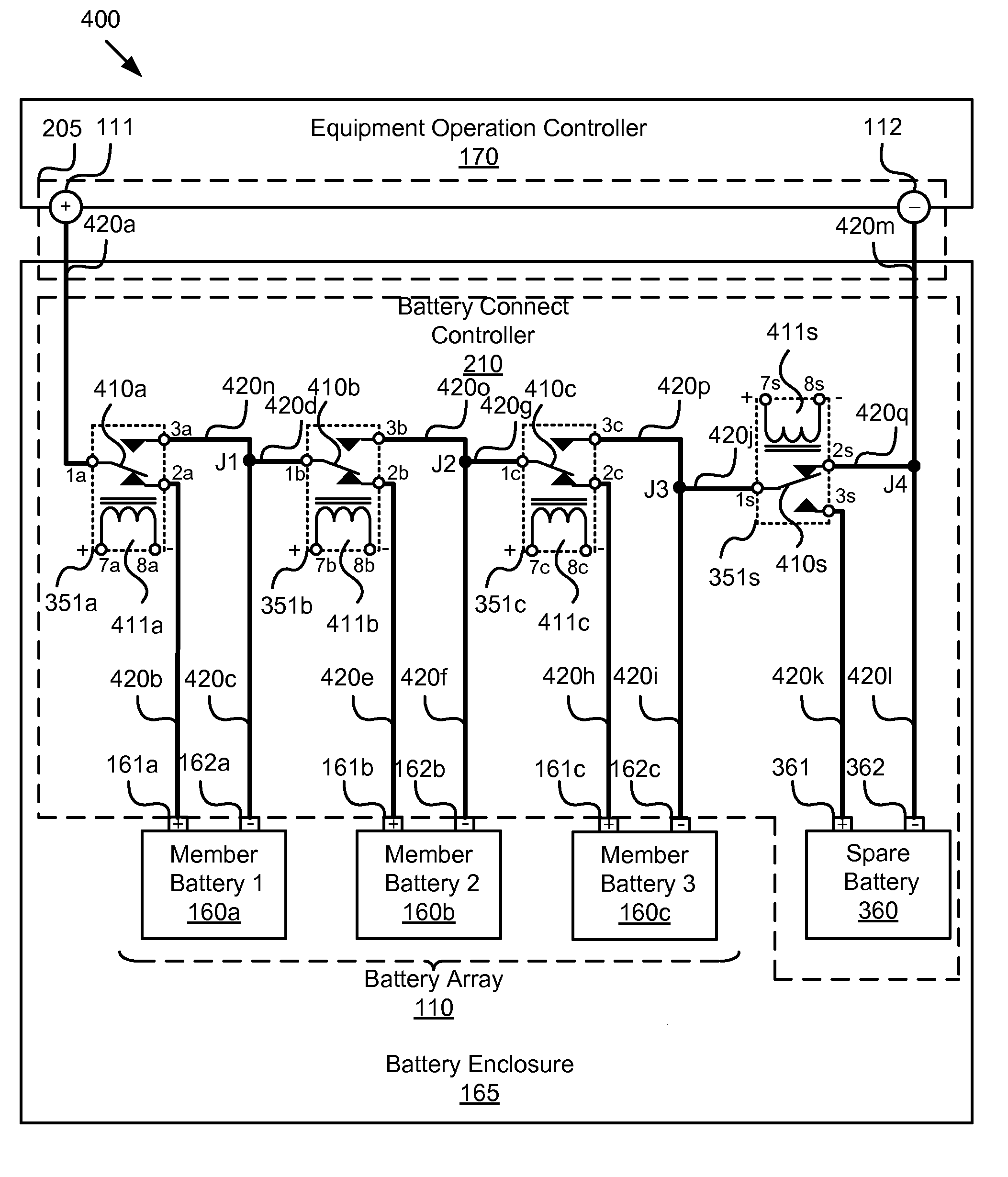
[0032]FIG. 7 is a schematic circuit diagram illustrating one embodiment of a member relay switch activation responsive to a control signal from the corresponding faulty member battery of FIG. 5 in accordance with the present invention;
[0033]FIG. 8 is a schematic circuit diagram illustrating one embodiment of a spare relay switch ac...

Problems solved by technology

Current battery technology is adequate for EVs with a range, for example, of 250 miles, but the batteries are still rather expensive and require elaborate safety mechanisms.
If the EV is moving when a serious cell failure occurs, the numerous built-in electronic sensors will detect the failure and will disconnect the high voltage from the vehicle.
Unfortunately, this will bring the vehicle to a stop, with all the high voltage and energy contained within the battery pack.
This can happen anywhere on the road, causing the vehicle driver to be stranded, possibly in the middle of nowhere.
That can place him / her in an unsafe situation.

Method used


Image

  • Apparatus, system, and method for automatically displacing a faulty in-use battery in a battery-powered electric equipment
  • Apparatus, system, and method for automatically displacing a faulty in-use battery in a battery-powered electric equipment
  • Apparatus, system, and method for automatically displacing a faulty in-use battery in a battery-powered electric equipment

Examples


Embodiment Construction

[0036]Many of the functional units described in this specification have been labeled as modules, in order to more particularly emphasize their implementation independence. For example, a module may be implemented as a hardware circuit comprising custom very large scale integration (“VLSI”) circuits or gate arrays, off-the-shelf semiconductors such as logic chips, transistors, or other discrete components. A module may also be implemented in programmable hardware devices such as field programmable gate arrays, programmable array logic, programmable logic devices or the like.

[0037]Modules may also be implemented in software for execution by various types of processors. An identified module of executable code may, for instance, comprise one or more physical or logical blocks of computer instructions, which may, for instance, be organized as an object, procedure, or function. Nevertheless, the executables of an identified module need not be physically located together, but may comprise ...


PUM


Abstract

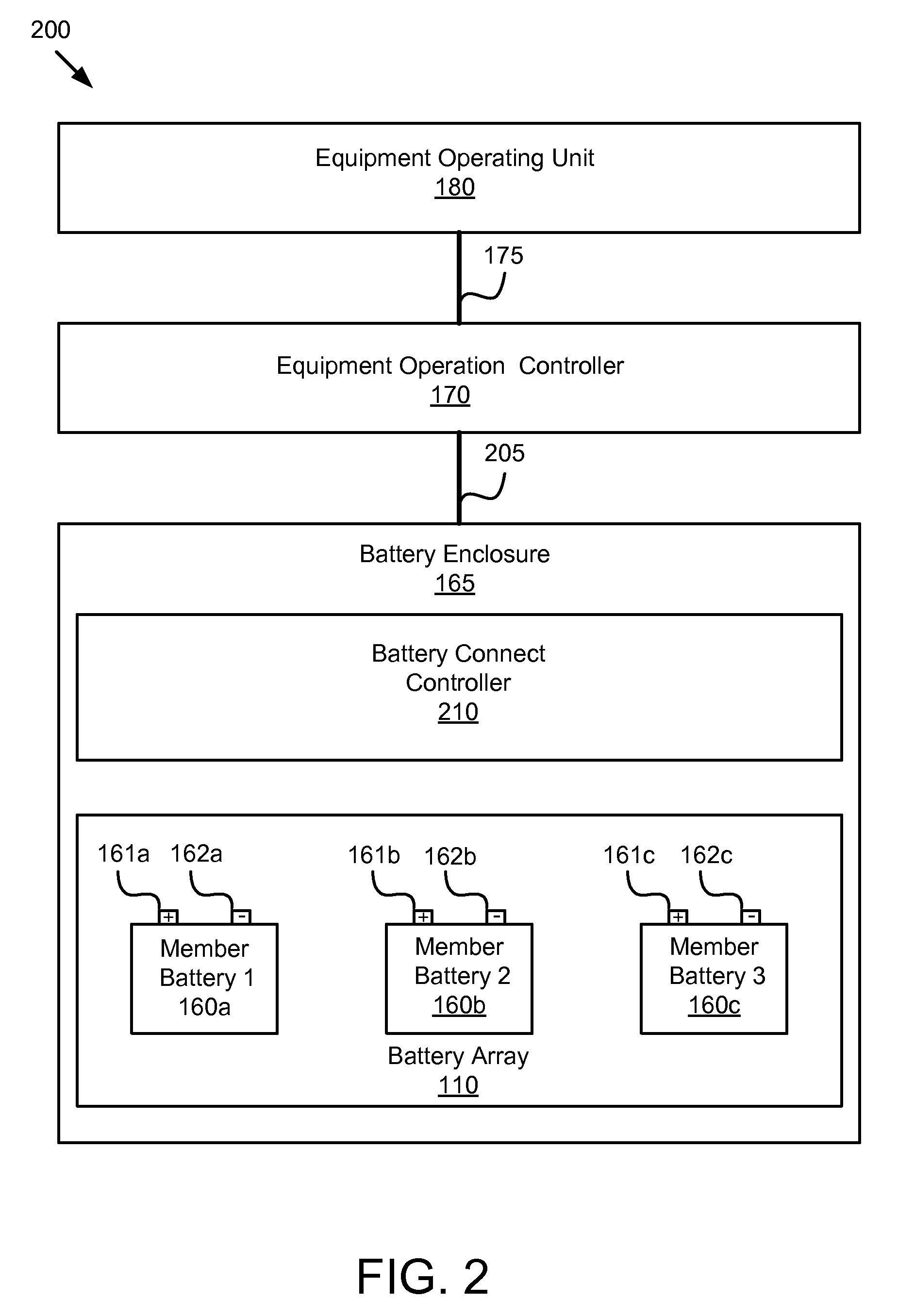
An apparatus, system, and method are disclosed for automatically displacing a faulty in-use member battery in an electric equipment, such as electric vehicle, powered by an array of member batteries configured to self detect battery fault conditions and output a control signal upon such detection. By use of a charged spare battery and deactivated single pole double throw relay switches with activation means for coupling all batteries, member batteries are normally interconnected in series electrically to provide a predetermined voltage, with the spare battery standing by. While the electric equipment is in operation, as soon as a member battery detects a fault, the corresponding relay switch is activated to cause the faulty member battery to be electrically bypassed by the battery array. Concurrently, the spare relay switch is activated to electrically connect the spare battery to the battery array in series, thereby displacing the faulty in-use member battery.

Description

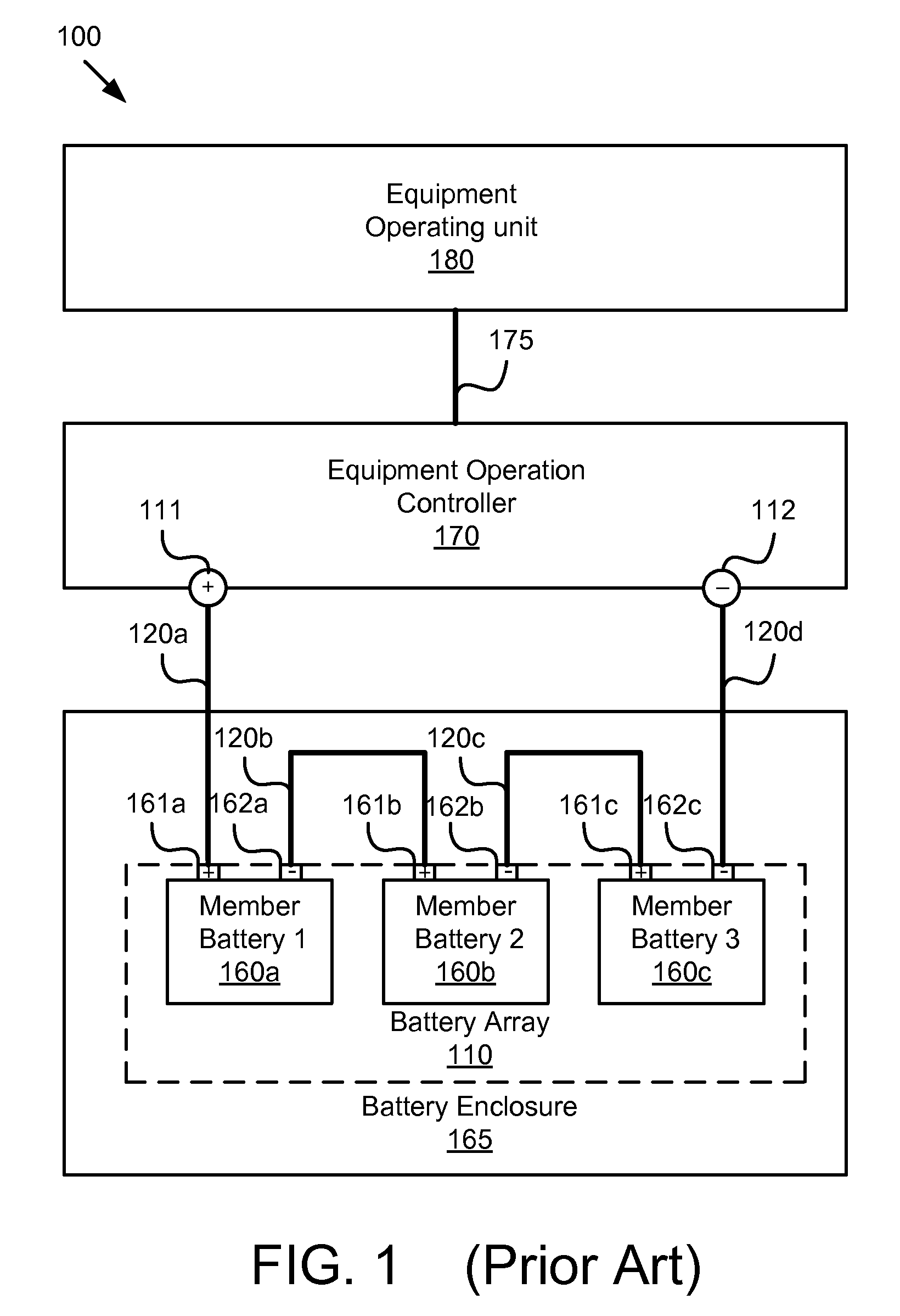
BACKGROUND OF THE INVENTION[0001]1. Field of the Invention[0002]This invention relates to multiple-battery electric systems, and more particularly relates to electric equipment, such as an electric vehicle, powered by a redundant array of batteries.[0003]2. Description of the Related Art[0004]Electric equipment, such as an electric vehicle (“EV”), utilizes chemical energy stored in rechargeable batteries which is converted to electricity. EVs use electric motors instead of, or in addition to, internal combustion engines. In the latter case, the EV is referred to as a hybrid electric vehicle (“HEV”). At the heart of an EV, there are three main components: batteries, electric motor controller, and electric motor. Batteries supply power to the electric motor controller, which controls the amount of voltage and current supplied to the electric motor based on the position of the accelerator pedal. Batteries used in EVs vary in type, number, voltage and placement. Operating voltage can be...

Claims


Application Information

Patent Timeline
IPC IPC(8): H02J7/00
CPCB60L3/0046B60L3/12B60L58/22B60L58/26B60L2240/545B60L2240/547B60L2240/549Y02T10/70
Inventor KING, ALLENLIANG, LAWRENCE C.
Owner STARVOLT
Learn More