
Processing device

a processing device and geometrie technology, applied in the field of geometrie process, to achieve the effect of reducing power consumption and cost, reducing clock frequency, and prolonging calculation tim

Active Publication Date: 2009-08-20
PANASONIC CORP
View PDF6 Cites 15 Cited by
  • Summary
  • Abstract
  • Description
  • Claims
  • Application Information

AI Technical Summary

Benefits of technology

[0012]With the above-described construction, the processing device causes the plurality of processors to share the vertex process in which computations are performed for each of the vertices constituting a polygon, when rendering a polygon mesh in which a three-dimensional object is modeled. The plurality of processors then share with each other processed vertex data obtained by the above computations. In this way, any processor can perform the polygon process. Since the plurality of processors share the processes, and each of the processors performs the vertex process and the polygon process in series, it is possible to resolve the unbalance of the timing in performing the vertex and polygon processes.
[0013]As a result, the processors are unlikely to have idle time, which makes it possible for the processors to give the full performance. Accordingly, even a processor having a low spec, such as a processor mounted on a mobile phone, can continuously render an image without interruption. Since a processor can take longer time in calculation, the processor can operate with a lower clock frequency. This is advantageous in terms of reducing power consumption and cost.
[0014]Also, in the processing device of the present invention, the internal construction of each of the plurality of processors is the same. Therefore, the above-described process can be realized by each of the processors running the same program. This makes it possible to expand the program without changing the program, even when changing the number of processors.
[0015]Here, the supply unit may have input / output units respectively for the processors, and each of the input / output units may receive sets of world coordinates from a plurality of registers that belong to processors different from a processor including the input / output unit, and transmit the sets of world coordinates to a computation unit that belongs to the processor including the input / output unit.
[0016]With the above-described structure, even when transformed coordinates, which are obtained by the vertex process of a computation unit, are stored in a register that belongs to the same processor as a processor in which the vertex process has been performed, the input / output unit reads the transformed coordinates if the transformed coordinates are required for the polygon process of a computation unit that belongs to another processor. In this way, all the computation units of the processors can perform the polygon process after the vertex process in series, thereby suppressing the occurrence of the unbalance of timing in performing the vertex process and the polygon process.
[0017]Here, the supply unit may have input / output units respectively for the processors, and each of the input / output units may receive a set of world coordinates that have been transformed by a computation unit that belongs to a same processor as a processor including the input / output unit, and transmit the set of world coordinates to a plurality of registers that belong to processors different from the processor including the input / output unit.

Problems solved by technology

This geometry process is a bottleneck in rendering a polygon mesh.

Method used


Image

  • Processing device
  • Processing device
  • Processing device

Examples


first embodiment

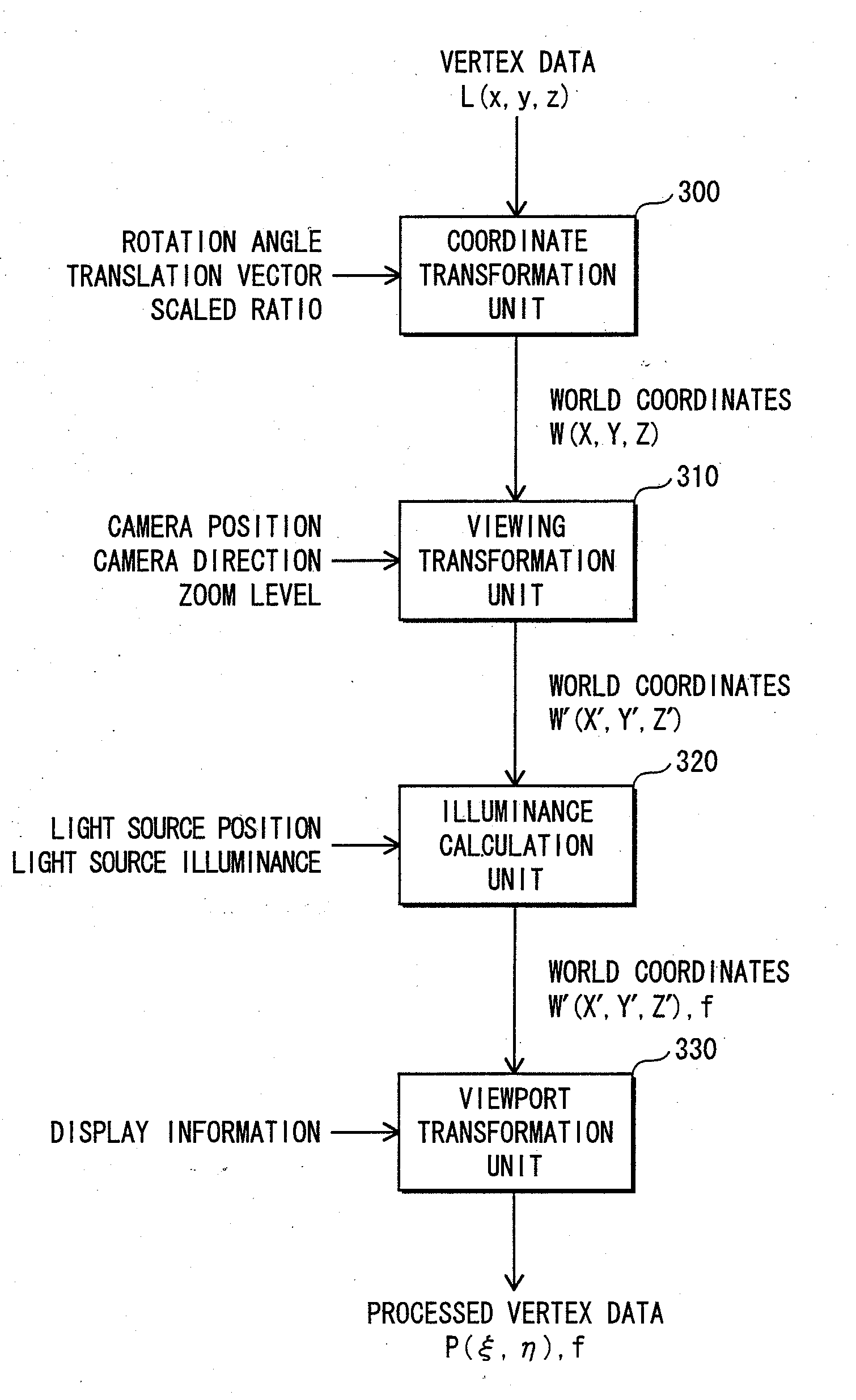
[0084]A processing device in a first embodiment of the present invention is incorporated in a mobile phone as shown in FIG. 1, and generates setup data that is for rendering projected images of three-dimensional objects on a display, based on a game program and game data that are recorded in a memory.

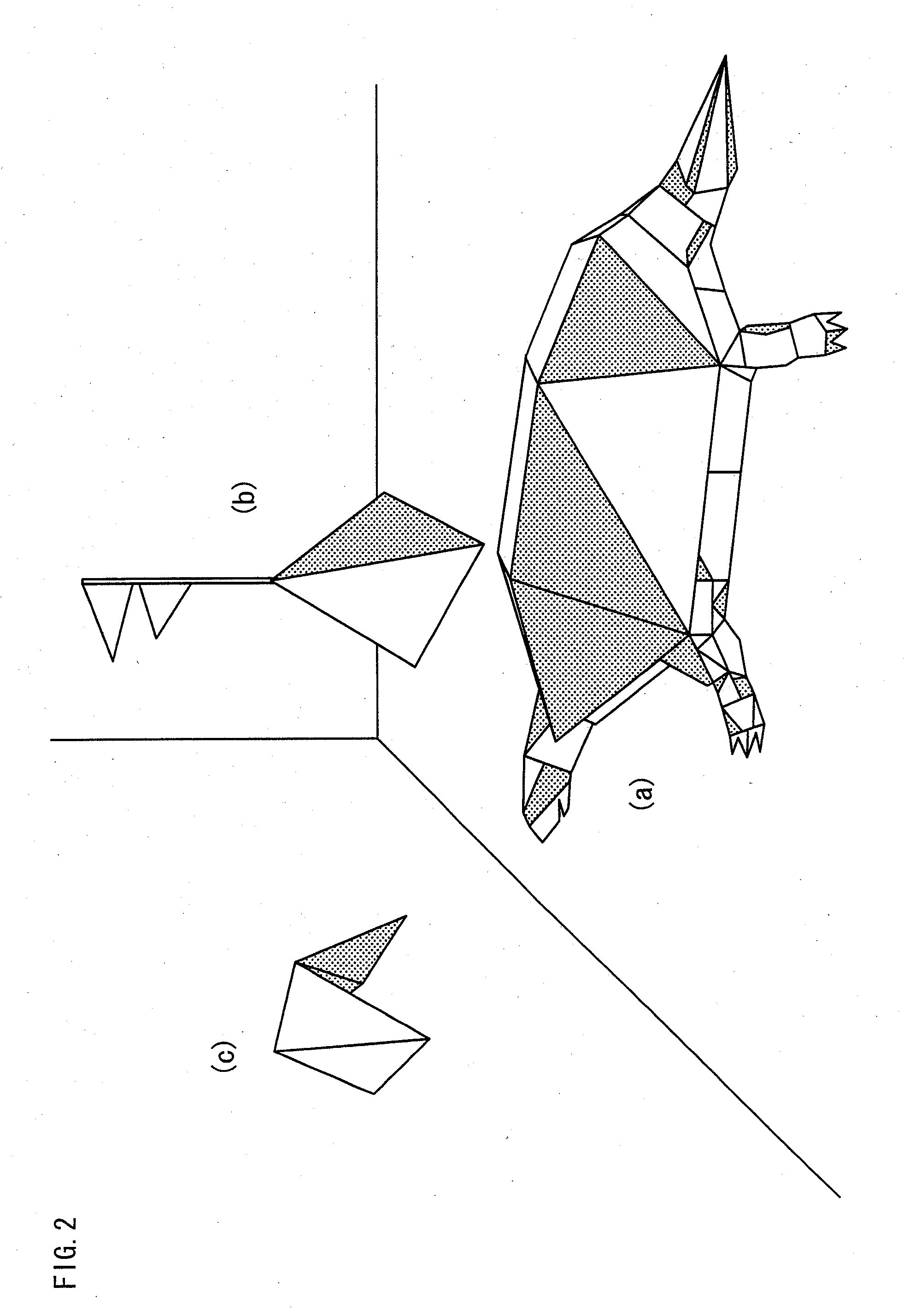
[0085]Here, the three-dimensional objects refer to characters and buildings in a game, and the game data refers to vertex data and polygon data. The vertex data includes coordinates of vertices of polygons when the above three-dimensional objects are modeled with use of the polygons. The polygon data includes information indicating which vertices are connected to create a polygon. Also, the game program includes microcode for calculating setup data from the vertex data and the polygon data. The setup data is a data string in which pixels of a display are in one-to-one correspondence with pixel information pieces that each indicate illuminance etc.

[0086]For example, FIG. 2 shows an examp...

second embodiment

[0165]In a second embodiment of the present invention, a description is provided of an example in which the structure of a plurality of processors in a processing device is different from the structure thereof in the first embodiment. In the first embodiment, (i) a computation unit that has performed a vertex process to obtain processed vertex data and (ii) a register that stores the processed vertex data belong to the same processor, and an input / output unit of another processor acquires the processed vertex data from the register of the processor. In the second embodiment, processed vertex data, which is obtained by a computation unit performing a vertex process on vertex data, is transmitted to an input / output unit. Then, the input / output unit transmits the processed vertex data to registers in other processors.

[0166]FIG. 20 shows a construction of a processing device in the second embodiment of the present invention. The processing device in the second embodiment includes the fo...

third embodiment

[0180]In a third embodiment of the present invention, a description is provided of an example in which a plurality of processors in a processing device cyclically receive and transmit the processed vertex data. In the first and the second embodiments, each of the input / output units receives and transmits processed vertex data between a plurality of registers. However, in the third embodiment, each of the input / output units transmits processed vertex data to only one of the input / output units.

[0181]FIG. 22 shows a construction of the processing device in the third embodiment of the present invention. The processing device in the third embodiment of the present invention includes: the four processors 200a, 200b, 200c, and 200d; the clock 240 for driving the processors; the distribution unit 250 for distributing vertex data to each processor; and the allocation unit 260 for allocating a processor that is for executing the polygon process. The third embodiment is the same as the first a...


PUM


Abstract

A processing device for performing a geometry process performed as preprocessing for rendering a three-dimensional object on a display by modeling the three-dimensional object using a polygon mesh. The geometry process includes a vertex process that is performed for each of the vertices of the polygon mesh by a different one of a plurality of processors, and processed vertex data obtained by the vertex process is notified among the processors so that a polygon process can be performed in each of the processors. Since each process or can continuously perform the polygon process immediately after the vertex process, it is possible to suppress the occurrence of the unbalance of timing in performing the vertex process and the polygon process, thereby efficiently performing computation while minimizing the wasteful idle time of the processors.

Description

TECHNICAL FIELD[0001]The present invention relates to a geometry process for rendering a polygon mesh.BACKGROUND ART[0002]In recent years, so-called “mobile games”, which operate in mobile apparatuses such as mobile phones, have been widely played, and a geometry process is critical in developing the games. Such mobile games include games in which a three-dimensional object is modeled by a combination of polygonal figures called polygons, and rendered on a display. The modeled three-dimensional object is referred to as “polygon mesh” because of a structure thereof in which polygons are filled in a mesh pattern. The polygon mesh is expressed by multiple vertices and edges that connect the multiple vertices. To simplify the calculation, triangles are usually selected to be used as a polygon. When rendering a polygon mesh, it is necessary to perform a vertex process and a polygon process. The vertex process is a process for performing coordinate transformation and illuminance calculati...

Claims


Application Information

Patent Timeline
Patent Type & Authority Applications(United States)
IPC IPC(8): G06T17/00G06T15/50G06T15/00
CPCG06T15/005
Inventor WAKAYAMA, YORIHIKO
Owner PANASONIC CORP
Learn More