Image information processing system and image information processing method

Inactive Publication Date: 2005-06-23
SHARP KK
View PDF3 Cites 26 Cited by
  • Summary
  • Abstract
  • Description
  • Claims
  • Application Information

AI Technical Summary

Benefits of technology

[0054] As described above, according to the present invention, since data is transferred in a compressed form, the data transfer amount can be reduced. A transfer time can be reduced in proportion to the reduction of the data transfer amount.
[0055] Assuming that data transfer is performed for the same amount of processing time as that for conventional techniques, the processing performance of a data transfer bus line can be increased up to an image size corresponding to the reciprocal of a compression rate. Therefore, the data transfer amount of the data transfer bus line can be increased without increasing the width of a bus line. A larger image size and an increased amount of moving image processing can be handled.
[0056] Also, assuming that data transfer is performed for the same amount of processing time as that for conventional techniques, the clock frequency of a data transfer bus line can be

Problems solved by technology

Therefore, the amount of data transferred on the conventional system bus line 106 is large, thus c

Method used


Image

  • Image information processing system and image information processing method
  • Image information processing system and image information processing method
  • Image information processing system and image information processing method

Examples


Example

Embodiment 1

[0088] Embodiment 1 of the present invention will be described below, where input non-compressed image data is compressed, the compressed image data is transferred and stored in a storage section 3 via a system bus line 6.

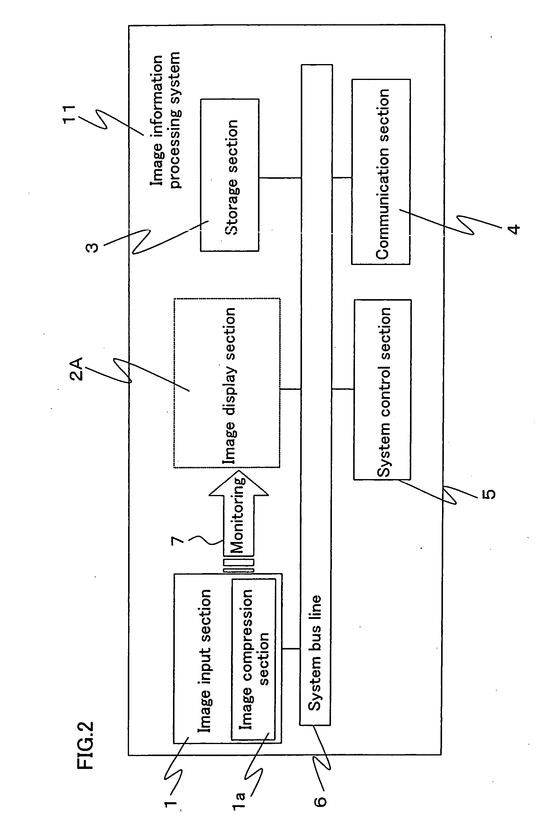
[0089]FIG. 2 is a block diagram showing a configuration of an image information processing system according to Embodiment 1 of the present invention.

[0090] As shown in FIG. 2, in the image information processing system 11, an image input section 1 for receiving an image (e.g., a CCD camera, a CCD image sensor, etc.), an image display section 2A for displaying an image (e.g., a liquid crystal display apparatus, etc.), a storage section 3 for accumulating image data, a communication section 4 for transmitting / receiving image data, and a system control section 5 for controlling each section of the image information processing system 11, are connected to one another via a system bus line 6 as a data transfer bus line.

[0091] The image input section 1 inc...

Example

Embodiment 2

[0098] Embodiment 2 of the present invention will be described below, where stored compressed image data is transferred via a system bus line 6 to an image decompression section, which in turn decompresses the data for replaying / displaying.

[0099]FIG. 3 is a block diagram showing a configuration of an image information processing system according to Embodiment 2 of the present invention.

[0100] As shown in FIG. 3, in the image information processing system 12, an image input section 1A for receiving an image (e.g., a CCD camera, a CCD image sensor, etc.), an image display section 2 for displaying an image (e.g., a liquid crystal display apparatus, etc.), a storage section 3 for accumulating image data, a communication section 4 for transmitting / receiving image data, and a system control section 5 for controlling each section of the image information processing system 12, are connected to one another via a system bus line 6 as a data transfer bus line.

[0101] The image d...

Example

Embodiment 3

[0106] Embodiment 3 of the present invention will be described below. In Embodiment 3, input non-compressed image data is compressed, and the compressed image data is transferred via a system bus line 6 to a storage section 3 and is stored in the storage section 3. Further, the stored compressed image data is transferred via the system bus line 6 to an image decompression section, which in turn decompresses the data for displaying / replaying.

[0107]FIG. 4 is a block diagram showing a configuration of an image information processing system according to Embodiment 3 of the present invention.

[0108] As shown in FIG. 4, in the image information processing system 13, an image input section 1 for receiving an image (e.g., a CCD camera, a CCD image sensor, etc.), an image display section 2 for displaying an image (e.g., a liquid crystal display apparatus, etc.), a storage section 3 for accumulating image data, and a system control section 5 for controlling each section of the i...


PUM


Abstract

An image information processing system is provided, which comprises an image input section for receiving image data, a storage section for storing the image data, and a control section for controlling the image input section and the storage section. The image input section, the storage section and the control section are connected together via a data transfer bus line. An image compression section for compressing the image data is provided within or adjacent to the image input section. The control section controls the image compression section to compress non-compressed image data input from the image input section, transfers the compressed image data via the data transfer bus line to the storage section, and controls the storage section to store the compressed image data.

Description

[0001] This nonprovisional application claims priority under 35 U.S.C. §119(a) on patent application No. 2003-38372 filed in Japan on Nov. 12, 2003, the entire contents of which are hereby incorporated by reference.BACKGROUND OF THE INVENTION [0002] 1. Field of the Invention [0003] The present invention relates to an image information processing system and an image information processing method for, for example, receiving, outputting (displaying), accumulating (storing), and transmitting / receiving static images or moving images. More particularly, the present invention relates to an image information processing system and method suitable for mobile electronic apparatuses, which are mainly used outdoors and require low power consumption, such as mobile telephones, personal digital assistants (PDAs), digital still cameras, mobile personal computers, and the like. [0004] 2. Description of the Related Art [0005] Conventionally, in the above-described types of image information processin...

Claims


Application Information

Patent Timeline
IPC IPC(8): H04N7/24G06F15/173H04N19/00H04N19/423
CPCH04N19/423H04N1/387H04N7/24
Inventor OBUCHI, YASUJIIMAI, SHIGEKI
Owner SHARP KK
Why Eureka
Try Eureka