Silicon microphone without dedicated backplate

a microphone and silicon technology, applied in the direction of diaphragm construction, loudspeaker diaphragm shape, semiconductor electrostatic transducer, etc., can solve the problems of complex and high-cost fabrication, manufacturing complications,

Active Publication Date: 2009-08-20
SHANDONG GETTOP ACOUSTIC
View PDF9 Cites 49 Cited by
  • Summary
  • Abstract
  • Description
  • Claims
  • Application Information

AI Technical Summary

Problems solved by technology

The inclusion of a dedicated backplate in the microphone sensing element normally leads to manufacturing complications due to its special definitions in material and processing method.
The required photolithographic masking levels as well as the processing issues relating to overlay and spacing between the diaphragm and backplate normally result in a complex and high cost fabrication.

Method used


Image

  • Silicon microphone without dedicated backplate
  • Silicon microphone without dedicated backplate
  • Silicon microphone without dedicated backplate

Examples


first embodiment

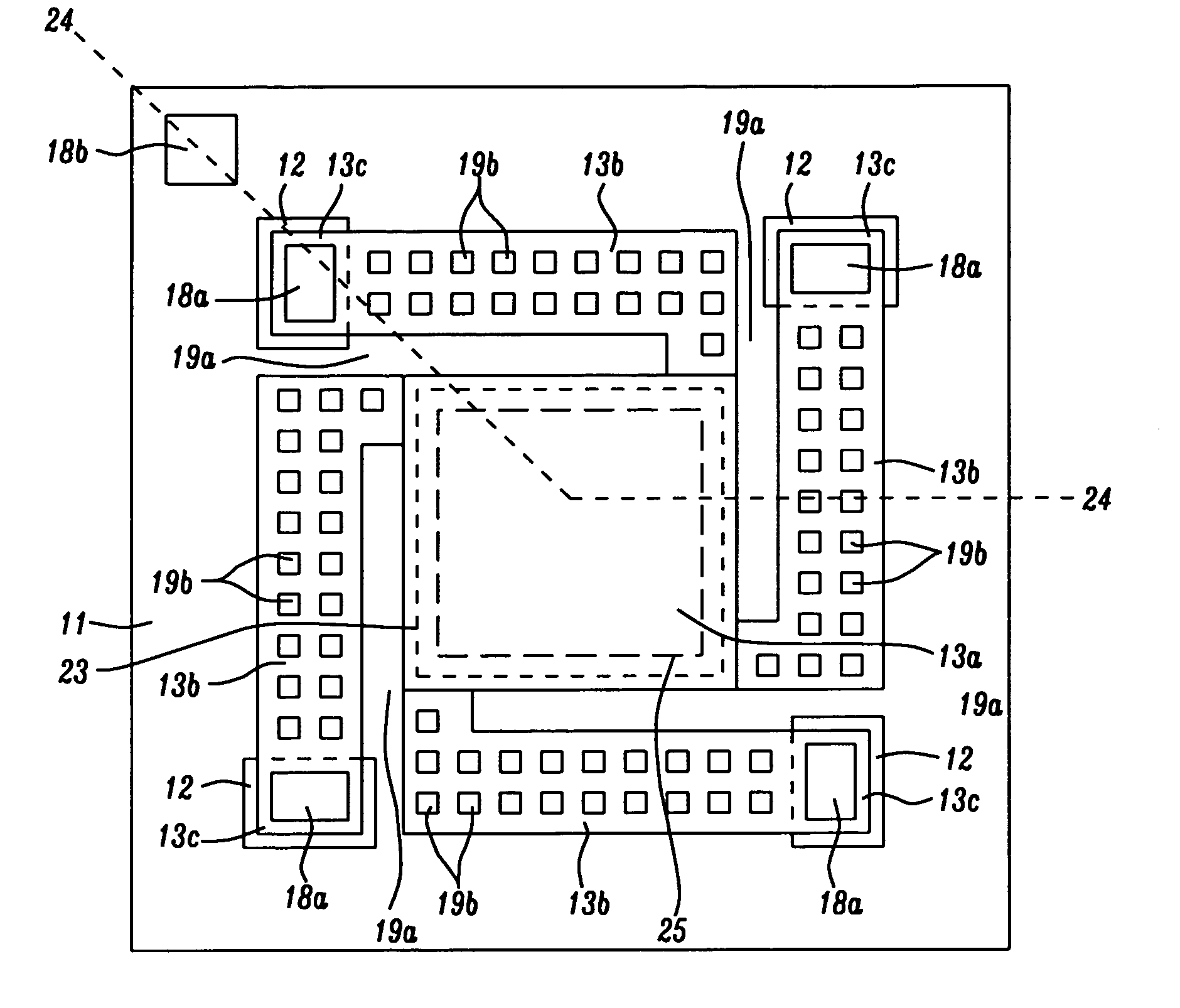
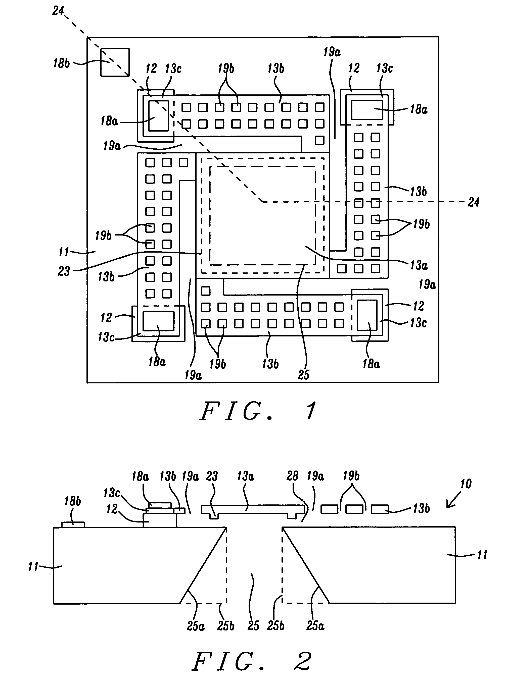
[0034]Referring to FIG. 1, a first embodiment is shown wherein the diaphragm 13a has a square or rectangular shape although a circular or polygonal shape is also acceptable. Each side adjoins an “L” shaped perforated spring 13b with holes 19b and that has a lengthwise direction which is parallel to the nearest diaphragm side. Each “L” shaped perforated spring adjoins the diaphragm 13a on one end and on the other end is connected to a rigid anchor pad 13c. In this configuration, each perforated mechanical spring 13b hereafter referred to as a perforated spring combines the features of the perforated spring 13b and perforated plate 13d that were originally described in related patent application Ser. No. 10 / 977,692. The term “spring” is used to describe a supporting means to control the compliance of the diaphragm 13a with respect to sound pressure. The vibration of the perforated spring 13b together with the diaphragm 13a also contributes to the capacitance change of the variable cap...

second embodiment

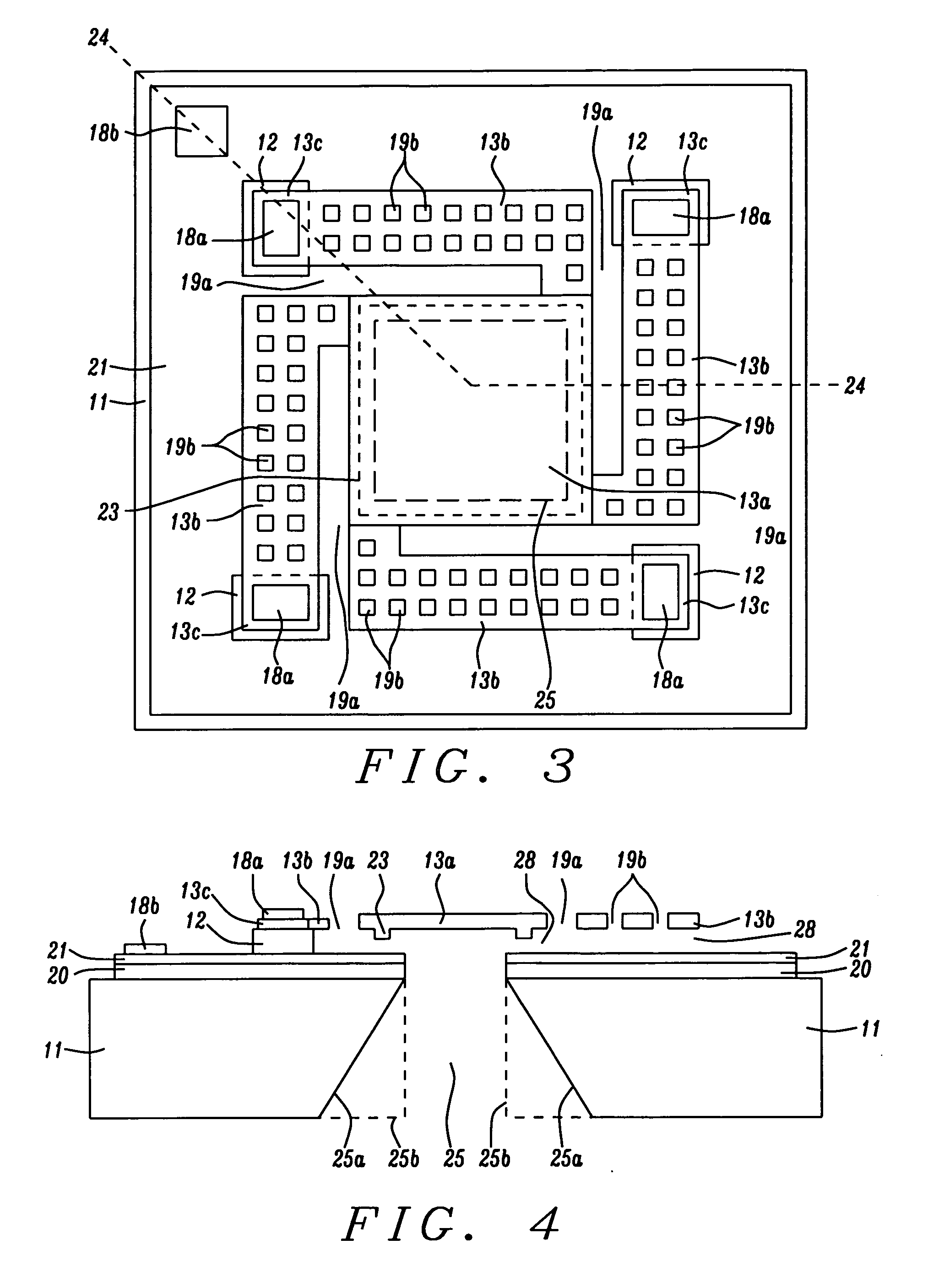
[0040]A cross-sectional view of the second embodiment is shown in FIG. 4. The dielectric layer 20 may be comprised of the same material as in dielectric layer 12 and is formed on the substrate 11. Conductive layer 21 is disposed on the dielectric layer 20 and may be comprised of a doped polysilicon layer, a doped silicon layer, or other metal materials. Note that the back hole 25 is extended vertically from the front side of the substrate 11 through the dielectric layer 20 and conductive layer 21 to allow a sound signal to pass through the back hole and air gap 28 and impinge on the back side of the diaphragm 13a between ribs 23. Dielectric layer 12 serves as a spacer between the conductive layer 21 and the plurality of rigid pads 13c and is formed only in locations below the rigid pads. A second electrode 18b is formed on the conductive layer 21 at one or more locations outside the perforated mechanical springs 13b with respect to diaphragm 13a.

[0041]Referring to FIG. 5a, a third ...


PUM


Abstract

Various embodiments of a silicon microphone sensing element without dedicated backplate are disclosed. The microphone sensing element has a circular or polygonal diaphragm with a plurality of perforated springs suspended above the front side of a conductive substrate. The diaphragm is aligned above one or more back holes in the substrate having a front opening smaller than the diaphragm. In one embodiment, a continuous perforated spring surrounds the diaphragm and has a shape that conforms to the diaphragm. A plurality of perforated beams connects the spring to rigid pads that anchor the movable diaphragm and spring. In another embodiment, there is a plurality of perforated springs having double or triple folding configurations and a plurality of perforated beams connecting the diaphragm to rigid pads. Also disclosed is a scheme to integrate the silicon microphone sensing element with CMOS devices on a single chip.

Description

RELATED PATENT APPLICATIONS[0001]This application is related to the following: Docket #SI06-002, Ser. No. 11 / 500,114, filing date Aug. 7, 2006; Docket #AL04-002, Ser. No. 10 / 977,692, filed on Oct. 29, 2004; Docket #AL04-001, Ser. No. 10 / 977,693, filing date Oct. 29, 2004; and Docket #S107-003, Ser. No. 11 / 973,075, filing date Oct. 5, 2007; all of which are assigned to a common assignee and are herein incorporated by reference in their entirety.FIELD OF THE INVENTION[0002]The invention relates to a sensing element of a silicon condenser microphone and a method for making the same, and in particular, to various embodiments of a silicon microphone structure without a dedicated backplate that has movable springs and diaphragm that are attached to rigid anchor pads.BACKGROUND OF THE INVENTION[0003]The silicon condenser microphone is typically comprised of two basic elements which are a sensing element and a pre-amplifier IC device. The sensing element is basically a variable capacitor co...

Claims


Application Information

Patent Timeline
Patent Type & Authority Applications(United States)
IPC IPC(8): H04R25/00
CPCH04R7/04H04R7/20H04R19/005H04R2307/207H04R31/00H04R2307/201H04R19/04H01L2224/48091H01L2924/00014
Inventor ZHE, WANG
Owner SHANDONG GETTOP ACOUSTIC
Why Eureka
Try Eureka