Electronic Circuit

a technology of electronic circuits and circuits, applied in the field of electronic circuits, can solve the problems of inability of conventional electronic circuits to cope with such a specification change, processor units sometimes encounter difficulties in fulfilling target performance, and enormous loss from the economic point of view, and achieve the effect of flexible operation sector and easy chang

Inactive Publication Date: 2009-08-20
PANASONIC CORP
View PDF6 Cites 0 Cited by
  • Summary
  • Abstract
  • Description
  • Claims
  • Application Information

AI Technical Summary

Benefits of technology

[0028]According to the structure of the present invention, it is possible to realize a highly flexible operating

Problems solved by technology

The processor unit is suitable to realize various functions by programs; however, the processor unit sometimes encounters difficulties in fulfilling a target performance.
However, the conventional electronic circuit shown in FIG. 7 has the following problems in calculation processing.
As another problem in the prior art, when specifications of an application are changed, for example, regarding the calculation of the first operating unit 5, from the current specifications of “to multiply t

Method used


Image

  • Electronic Circuit
  • Electronic Circuit
  • Electronic Circuit

Examples


embodiment 1

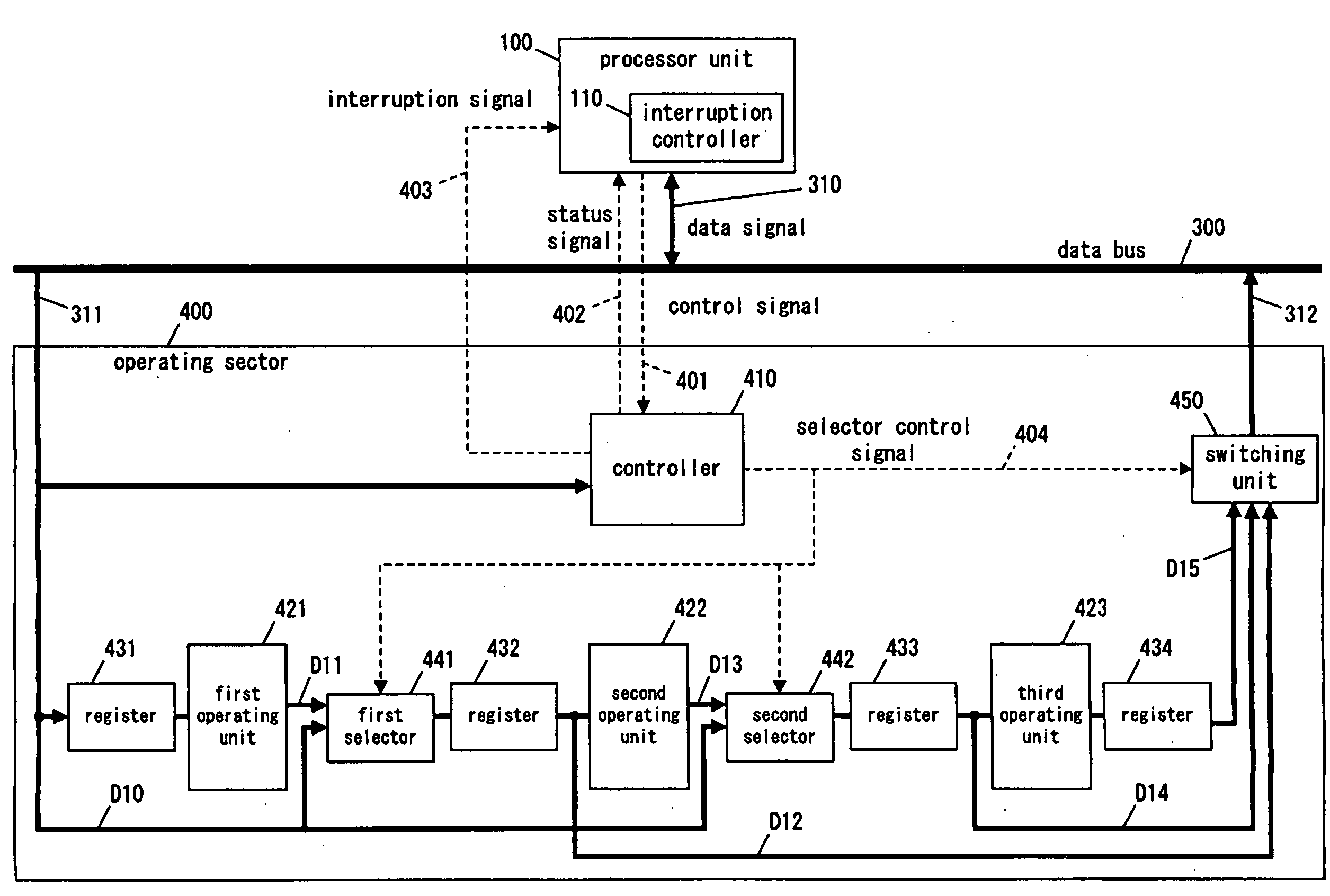
[0038]FIG. 1 is a block diagram of an electronic circuit in Embodiment 1 of the present invention.

[0039]The electronic circuit of the present embodiment comprises a processor unit 100 and an operating sector 200 connected to the processor unit 100. The operating sector 200 includes a first operating unit 221, a second operating unit 222, a first selector 241, a second selector 242, and a controller 210.

[0040]The controller 210, on receipt of the instruction from the processor unit 100, controls the execution of the first operating unit 221 and the second operating unit 222, and the switchover of the first selector 241 and the second selector 242.

[0041]The following explains a case where the operating sector 200 of the present embodiment normally executes the predetermined processing. The first operating unit 221 inputs data D1 from the processor unit 100 and performs predetermined processing. The first selector 241 switches the connection to a contact 1a, and selects output data D2 ...

embodiment 2

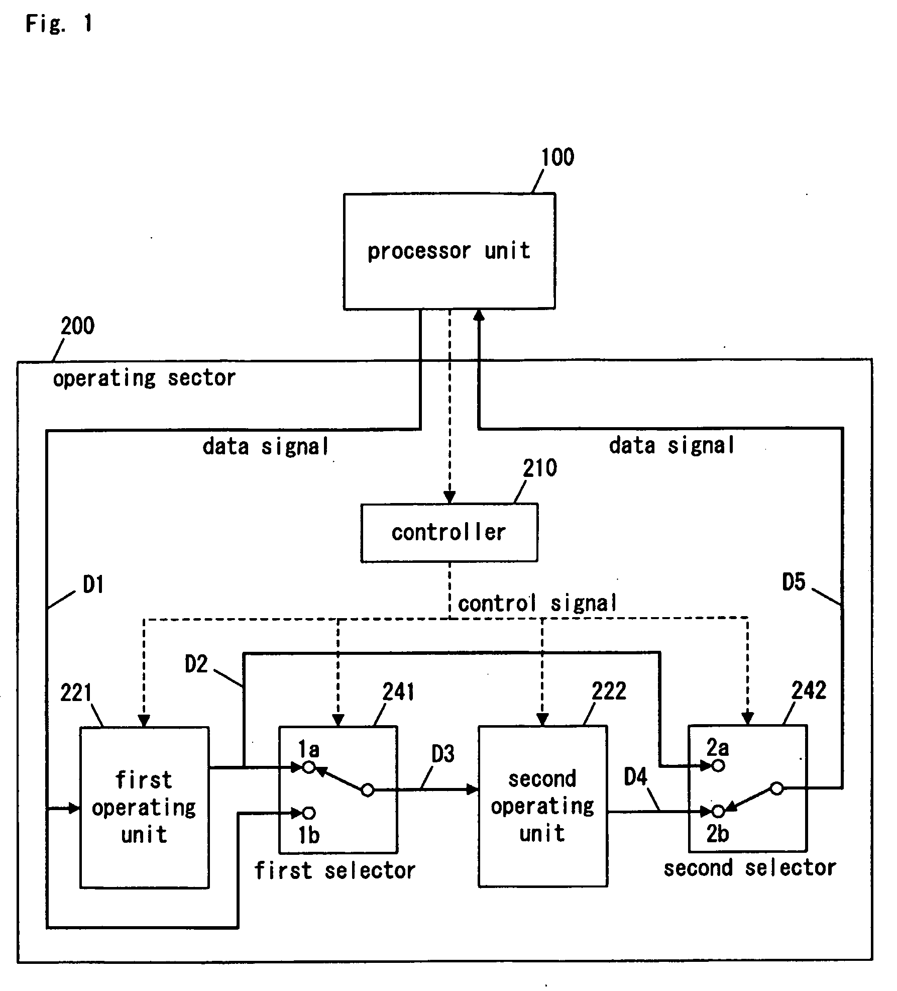
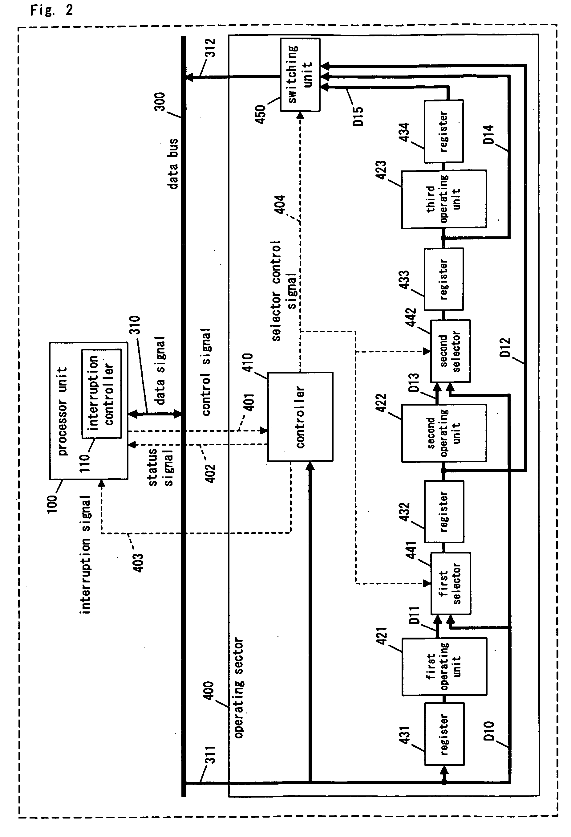
[0048]FIG. 2 is the block diagram of the electronic circuit in Embodiment 2 of the present invention.

[0049]The electronic circuit of the present embodiment comprises a bus 300, the processor unit 100 connected to the bus 300, and an operating sector 400 connected to the bus 300.

[0050]The processor unit 100 includes an interruption controller 110.

[0051]The operating sector 400 includes a first operating unit 421; a second operating unit 422; a third operating unit 423; registers 431, 432, and 433, each operable to set data to the respective succeeding operating unit; a register 434 operable to store the calculation result of the third operating unit 423; a first selector 441 operable to switch-over the input of the register 432; a second selector 442 operable to switch-over the input of the register 433; a switching unit 450 operable to select one of the outputs of the operating units; and a controller 410 operable to control the first selector 441, the second selector 442, the switc...


PUM


Abstract

An electronic circuit comprises a bus (300), a processor unit (100), and an operating sector (400). The operating sector (400) includes a first operating unit (421), a second operating unit (422), a third operating unit (423), registers (431) to (434), a first selector (441), a second selector (442), a switching unit (450), and a controller (410). For example, when the processor unit (100) substitutes processing of the second operating unit (422), the switching unit (450) selects output data (D12) of the first operating unit (421), and the second selector (442) selects processing result (D10) that is performed by the processor unit (100). Then, the switching unit (450) inputs the result into the third operating unit (423).

Description

TECHNICAL FIELD[0001]The present invention relates to an electronic circuit in which a part of processing of operating units thereof can be substituted by a processor unit thereof.BACKGROUND ART[0002]An electronic circuit possessing a processor unit is used as one of the methods to install a certain application in equipment. The processor unit is suitable to realize various functions by programs; however, the processor unit sometimes encounters difficulties in fulfilling a target performance. There is a tendency that in the electronic circuit for signal processing used for the latest AV equipment etc., the target performance required for the electronic circuit is alternatively fulfilled by adding a high-speed operating unit to the electronic circuit in order to assist the performance of the processor unit.[0003]As disclosed in Document 1 (“Development of One Chip LSI for MPEG 2 Video Encoder”; Tadao Matsuura et al., Sharp Technical Report, No. 72, December 1998, pp. 42-45.), the lat...

Claims


Application Information

Patent Timeline
IPC IPC(8): G06F13/24
CPCG06F11/2028G06F11/2038G06F11/2035
Inventor NAKAMURA, TSUYOSHI
Owner PANASONIC CORP
Why Eureka
Try Eureka