Venturi pinwheel and sea anchor wave energy conversion systems

a technology of wave energy conversion and pinwheel, which is applied in the direction of sea energy generation, machines/engines, mechanical equipment, etc., can solve the problems of low efficiency of water movement, and low efficiency of devices, so as to reduce the world's reliance on fossil fuels, high efficiency, and low maintenance

Active Publication Date: 2009-08-27
LONE GULL HLDG LTD
View PDF40 Cites 30 Cited by
  • Summary
  • Abstract
  • Description
  • Claims
  • Application Information

AI Technical Summary

Benefits of technology

[0050]Unlike wave-energy devices that extract energy from tidal currents or changes in sea level, and those that operate on the shoreline, or in the shallower waters near shore, deep-sea wave-energy devices may be deployed on a massive scale because so much of the earth's surface is covered by the deep sea. This is an important advantage for any alternative

Problems solved by technology

Very few are capable of operating in the deepest parts of the ocean, without benefit of a direct connection to the ocean floor.
Such a device does not generate much power.
Even though the force driving the water back and forth through a suspended turbine would be great, the speed of the water's movement is relatively slow.
At this speed, it would be difficult to extract a significant amount of energy from the flowing water with a simple turbine because the amount of power that can be extracted from a flowing stream of water by a turbine is proportional to the cube of its velocity.
Since ocean waves rise and fall with a relatively slow speed (the maximum of which is generally only one or two meters per second), it is difficult to extract much energy from the water constrained to flow through a propeller.
The known tidal flow turbines are large, complex and expensive.
Their deployment is difficult.
Moreover, large deployments are not possible, i.e., there are a limited number of locations where these devices can operate.
They do not generate energy continuou

Method used


Image

  • Venturi pinwheel and sea anchor wave energy conversion systems
  • Venturi pinwheel and sea anchor wave energy conversion systems
  • Venturi pinwheel and sea anchor wave energy conversion systems

Examples


Embodiment Construction

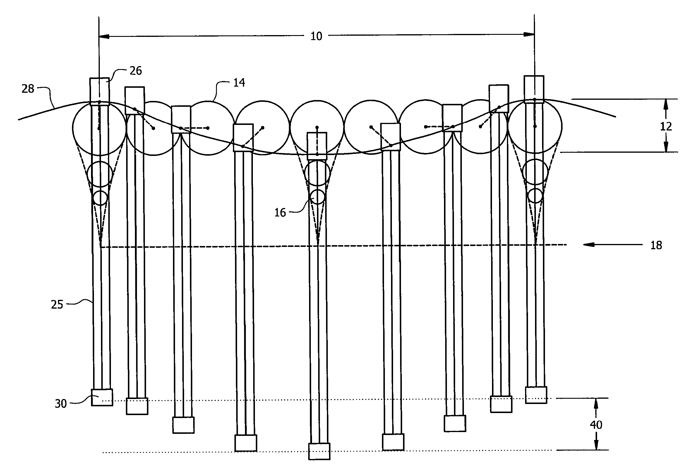
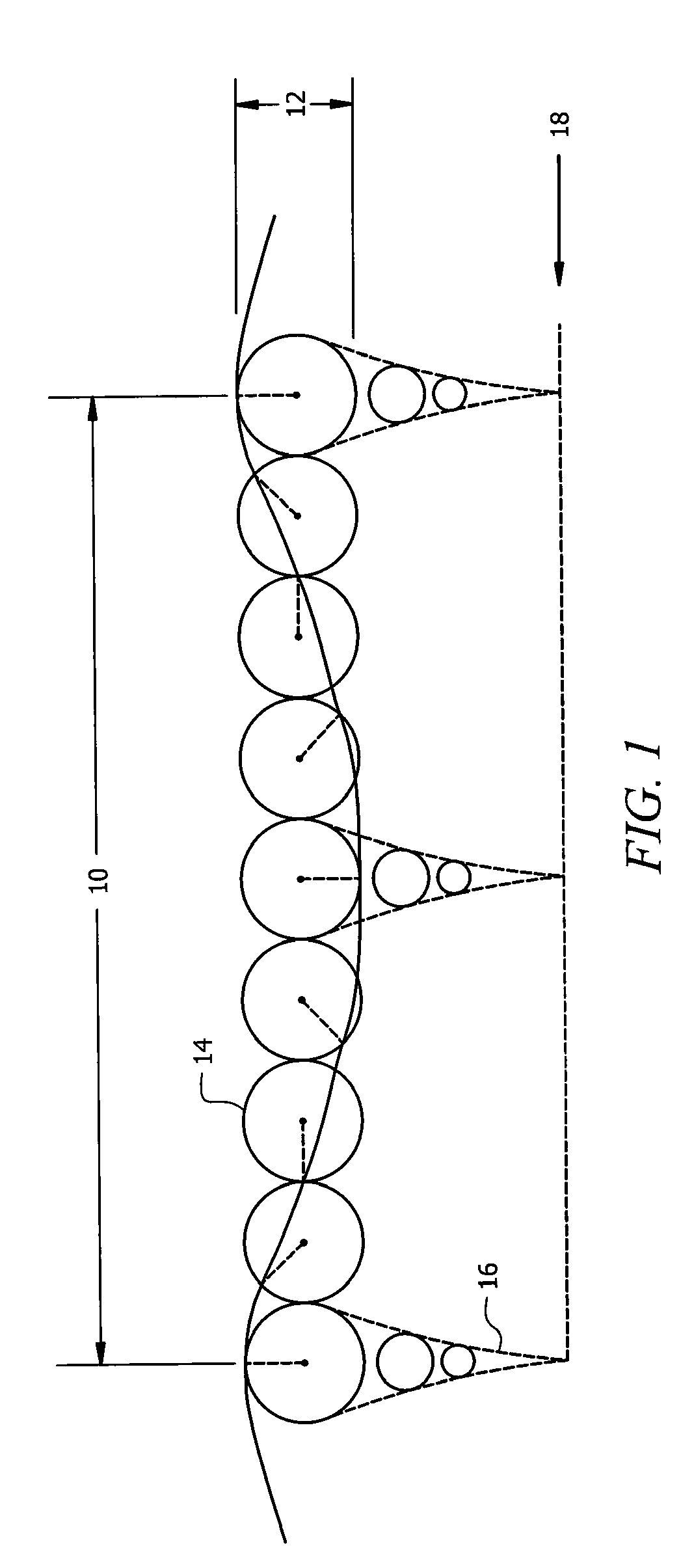
[0087]FIG. 1 illustrates properties of deep-water swells that are particularly relevant to the invention disclosed herein. The wavelength 10 of a deep-water wave is the distance over which the waveform repeats itself, i.e., from wave crest to wave crest. The height to which the wave crest is raised above the corresponding wave troughs is the wave height or amplitude and is denoted 12.

[0088]Water molecules and other particles contributing to the propagation of deep-water waves have circular, as distinguished from elliptical, orbits 14. The radii of such orbits decrease exponentially with increasing depth as indicated by the reference numeral 16. The radii become vanishingly small as the depth approaches one-half the wavelength of the waves. This special depth is called the wave base 18. A deep-water wave does not move the water located below the wave base to any significant degree. The water below this depth, and any objects floating in it are substantially stationary even when waves...


PUM


Abstract

A device that converts wave energy to electrical or chemical energy includes a buoy adapted to float on a water surface, a venturi tube, and a rigid or flexible means of connecting the buoy and the venturi tube. The venturi tube defines a lumen through which water flows downwardly when the buoy moves upwardly and upwardly when the buoy moves downwardly. A constriction is formed in the lumen to create a venturi effect for water flowing upwardly and downwardly through the lumen. A turbine is positioned in the lumen at the constriction where water flow is at a maximum rate. The turbine is connected to a generator so that the venturi effect is harnessed to generate power. Multiple embodiments are included.

Description

CROSS-REFERENCE TO RELATED APPLICATIONS[0001]This application is a non-provisional of provisional patent application filed by the same inventor on Feb. 22, 2008, entitled “‘Venturi,’‘Chambered Venturi’ and ‘Sea-Anchor’ Wave Energy Conversion Systems.’”BACKGROUND OF THE INVENTION[0002]1. Field of the Invention[0003]This invention relates, generally, to wave energy conversion devices that convert abundant natural energy present in oceans and other bodies of water into electrical or chemical energy such as the creation of hydrogen from water through electrolysis.[0004]2. Description of the Prior Art[0005]Water turbines have been used to extract useful energy from moving water, or water under pressure, for thousands of years. Many different types of water turbines have been invented and used in the past to extract energy from water under a variety of circumstances, and characterized by a variety of characteristics, with optimal efficiencies. e.g., Francis turbines, Pelton turbines, Kapl...

Claims


Application Information

Patent Timeline
IPC IPC(8): F03B13/20
CPCY02E10/38F05B2240/242F03B13/22F05B2250/25Y02E10/30
Inventor MOFFAT, BRIAN LEE
Owner LONE GULL HLDG LTD
Why Eureka
Try Eureka